Elastic strip fixing machine

An installation machine and installation mechanism technology, which is applied to laying tracks, roads, tracks, etc., can solve the problems of inability to meet the requirements of rapid installation, high labor intensity of workers, low construction efficiency, etc., and achieves reduced labor intensity of workers, simple structure, and low construction efficiency. Efficiency improvement effect

Inactive Publication Date: 2011-05-25
郑州铁路利达实业有限公司
View PDF0 Cites 0 Cited by
  • Summary
  • Abstract
  • Description
  • Claims
  • Application Information

AI Technical Summary

Problems solved by technology

[0002] Spring bars need to be installed during the laying of railway tracks. Since there are no special tools, it is completely manual. The construction is slow and cannot meet the requirements of rapid installation. The labor intensity of workers is high and the construction efficiency is low.

Method used


Image

  • Elastic strip fixing machine
  • Elastic strip fixing machine
  • Elastic strip fixing machine

Examples


Embodiment Construction

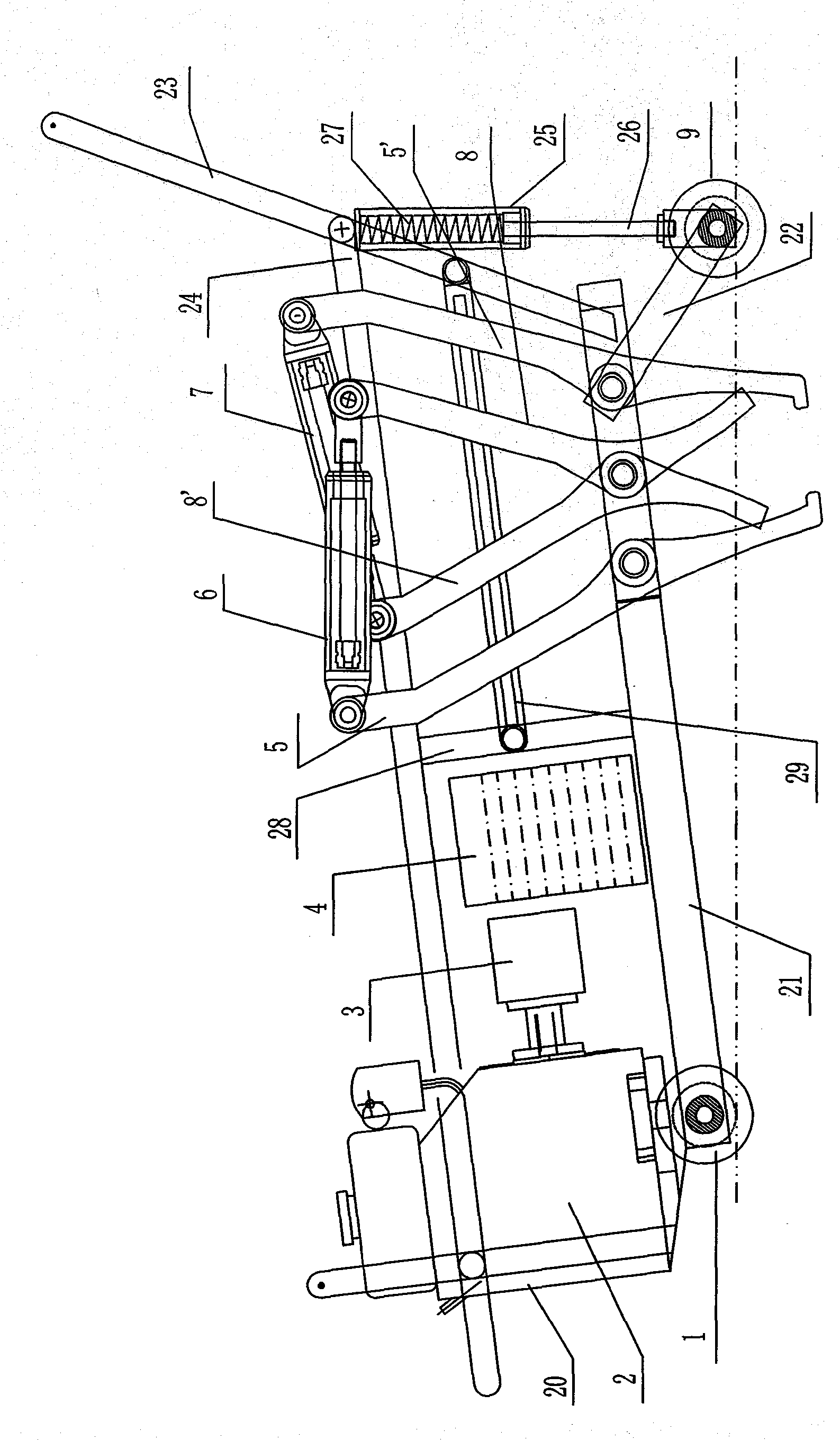
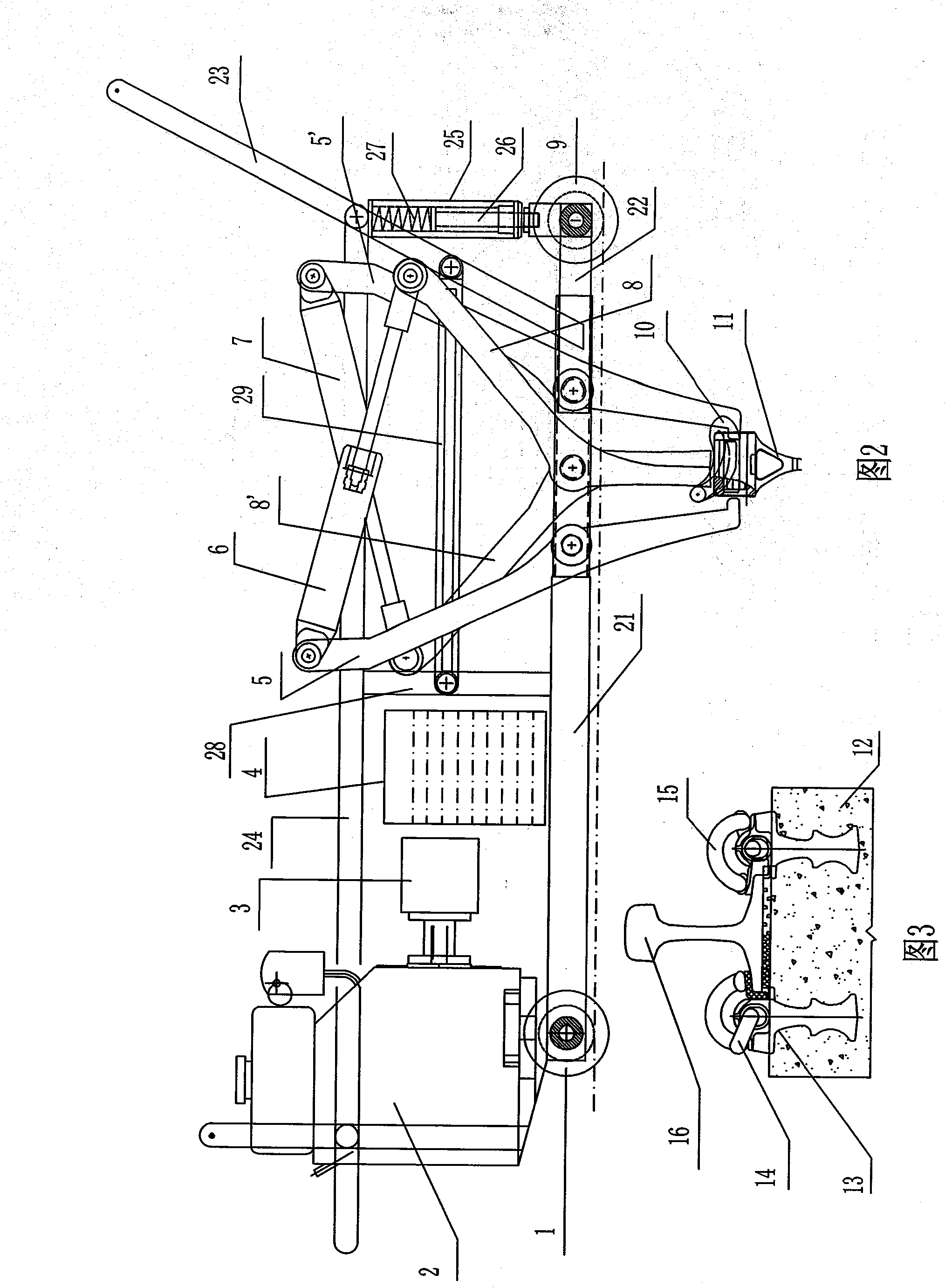
[0015] Elastic installation machine, comprising frame 20 with a traveling mechanism, three radial connecting holes are arranged at intervals on the lower frame 21 of the frame, and elastic installation mechanisms are arranged on both sides of the lower frame 21 of the frame, and the elastic installation mechanism includes an oil cylinder 6, 7 and the support arms 5, 5' and the outward crank arm shift forks 8, 8' which are respectively hinged with the bottom end of the oil cylinder and the top of the piston, the support arm 5 and the crank arm shift fork 8 of the left elastic strip installation mechanism pass through the front The two connection holes are hinged with the lower frame 21 of the frame, and the lever arm shift fork 8' and the support arm 5' of the right side spring bar installation mechanism are hinged with the lower frame 21 of the frame through the rear two connection holes in sequence. The lower ends of the support arms 5, 5' are horizontally bent towards the cra...


PUM


Abstract

A spring bar fitting machine belongs to the railway track laying tool technical field, comprising a frame with a walking mechanism, a side surface of the lower part of the frame is provided with a spring bar fitting mechanism which comprises a cylinder, a supporting arm and an outward turn arm shifting-fork which are respectively hinged with the bottom end of the cylinder and the top end of a piston, the middle part of the supporting arm and the front interval and the rear interval of an inflection point of the turn arm shifting-fork are hinged with the lower part of the frame, the cylinder is connected with an oil pump through a pipe with a control valve, the oil pump is connected with a power, the rear part of the frame is provided with a spring bar fitting mechanism lifting mechanism. The invention is of simple structure, convenient operation and high construction efficiency.

Description

technical field [0001] The invention belongs to the technical field of tools for laying railway tracks, and in particular relates to a spring bar installation machine. Background technique [0002] Spring bars need to be installed during the laying of railway tracks. Since there are no special tools, it is completely done manually. The construction is slow and cannot meet the requirements of rapid installation. The labor intensity of workers is high and the construction efficiency is low. Contents of the invention [0003] The purpose of the present invention is to provide a spring installation machine with high construction efficiency. [0004] In order to achieve the above-mentioned purpose, the present invention adopts the following technical solutions: the spring mounting machine includes a frame with a traveling mechanism, and the bottom side of the frame is provided with a spring mounting mechanism, and the spring mounting mechanism includes an oil cylinder and is co...

Claims


Application Information

Patent Timeline
Patent Type & Authority Patents(China)
IPC IPC(8): E01B29/24
Inventor 王少斐王树伟许洪勋张振东
Owner 郑州铁路利达实业有限公司
Why Eureka
Try Eureka