Coil locating structure of electronic expansion valve

A technology of electronic expansion valve and valve body, which is applied in the direction of valve operation/release device, valve details, valve device, etc., which can solve problems such as product failure, aging of encapsulation layer, and influence on coil insulation performance, so as to ensure normal operation , the effect of resisting high-frequency impact

Active Publication Date: 2011-10-12
ZHEJIANG SANHUA INTELLIGENT CONTROLS CO LTD
View PDF2 Cites 0 Cited by
  • Summary
  • Abstract
  • Description
  • Claims
  • Application Information

AI Technical Summary

Problems solved by technology

[0005] As mentioned above, since the valve body and the coil (stator) are movable and assembled together, under low-frequency vibration (such as assembled in a stationary refrigeration system, such as a common household air conditioner), the valve body and the coil (stator) The active assembly structure can withstand the impact and maintain its assembly relationship to meet the requirements of use; but under high-frequency vibration (such as assembled in a moving refrigeration system, common such as automotive air conditioners), the valve body and coil (stator) activities The assembly structure is difficult to withstand the impact, and it is prone to failure in the circumferential and axial positioning of the coil
[0006] Further, the structure of the aforementioned existing electromagnetic expansion valve is very unfavorable to resist relatively harsh external environment because its coil is directly exposed to the working environment. Then wind the winding and set the magnetizer (the magnetizer of this structure is exposed to the outside) structure, the coil magnetizer is easy to rust and cause the product to fail; and the outer plastic (that is, after the internal structure of the coil is assembled, then the plastic wrap, the The plastic wrapping layer of the structure is located in the outermost layer) structure of the coil, the aging of the wrapping layer will be aggravated, which will affect the insulation performance of the coil

Method used


Image

  • Coil locating structure of electronic expansion valve
  • Coil locating structure of electronic expansion valve
  • Coil locating structure of electronic expansion valve

Examples


Embodiment 1

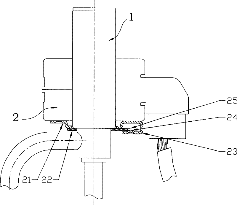
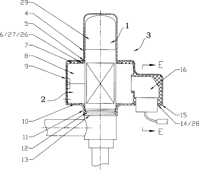
[0028] Such as figure 2 The electronic expansion valve shown to realize the positioning of the coil on the valve body includes a valve body 1 and a coil 2. The coil 2 has a winding part 8 and a socket part 16. There is an axial through hole 5 in the center of the winding part 8. The axial The through hole 5 is sleeved on the valve body 1, and a positioning member is provided between the coil 2 and the valve body 1, the details are:

[0029] The positioning member includes a bottom plate 10 and an outer cover 3;

[0030] The bottom plate 10 is fixed on the valve body 1 and supports the coil 2;

[0031] The outer cover 3 covers the outside of the coil 2 and has an axial positioning portion 26 corresponding to the bottom plate 10;

[0032] The outer cover 3 is fixedly connected to the base plate 10, and the axial positioning portion 26 presses the coil 2 on the base plate;

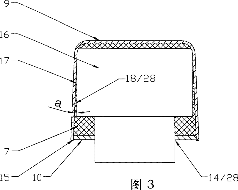
[0033] On the bottom plate 10 or the outer cover 3, a circumferential positioning part 28 is provided ...

Embodiment 2

[0041] Such as Figure 4 The electronic expansion valve that realizes the positioning of the coil on the valve body is illustrated on the basis of the structure of the first embodiment, and the differences between it and the first embodiment are explained, and the similarities will not be repeated:

[0042] The pressing part 27 is an outer flange 6 arranged at the lower end of the closing cap 4, the outer flange 6 is located on the lower side of the axial through hole 5 and is pressed on the upper end of the coil by the cover wall at the axial through hole 5, No filler is filled in the space between the housing 3 and the coil 2 .

Embodiment 3

[0044] Such as Figure 5 The electronic expansion valve that realizes the positioning of the coil on the valve body is illustrated on the basis of the structure of the first embodiment, and the differences between it and the first embodiment are explained, and the similarities will not be repeated:

[0045] The outer cover 3 includes a main part 9 corresponding to the coil 2 and a closing cap 4 extending from the main part to cover the protruding section 29. The pressing part 27 is a plane 20 on which the main part 9 is pressed on the upper end of the coil 2. Between the outer cover 3 and the The spaces between the coils 2 are not filled with fillers.


PUM


Abstract

A coil position structure of electronic expansion valve comprises a valve body and a coil; a position member arranged between the coil and the valve body comprises a soleplate and an outer cover; the soleplate is fixed on the valve body and supports the coil; the outer cover covers outside the coil and is provided with an axial position part corresponding to the soleplate; the outer cover is fixedly connected with the soleplate; the coil is clamped on the soleplate by the axial position part; a circumferential position part clashed on a socket part is arranged on the soleplate or the outer cover. Through the axial position part and the circumferential position part, the invention achieves the position of the coil on the valve body to prevent the coil rotating in circumferential direction and moving in axial direct; as the outer cover is fixedly connected with the soleplate which is fixed on the valve body; two position parts are fixed structures in an assembling state, thereby effectively resisting high-frequent impact and maintaining the assembling relation between the coil and the valve body and further providing a protective barrier to ensure a normal operation.

Description

technical field [0001] The invention relates to components used in a refrigeration system, in particular to an electronic expansion valve for adjusting the refrigerant flow and realizing the positioning of the coil on the valve body. Background technique [0002] In the refrigeration system, the electronic expansion valve is an indispensable component used to adjust the flow of refrigerant in the system. There are also various patent documents that have been published about its structure. Generally speaking, it is composed of a valve body and a coil. , through the power provided by the coil, the action of the relevant parts in the valve body can be controlled to open or close the valve port and adjust the opening of the valve port, thereby realizing the control of the refrigerant. Most of the valve body and the coil of the existing electronic expansion valve are movably assembled together, that is, the coil is assembled on the valve body through a movable positioning device....

Claims


Application Information

Patent Timeline
Patent Type & Authority Patents(China)
IPC IPC(8): F16K31/06
Inventor 张胜昌詹才意魏先让
Owner ZHEJIANG SANHUA INTELLIGENT CONTROLS CO LTD
Why Eureka
Try Eureka