
Imaging lens

一种摄像透镜、透镜的技术,应用在透镜、光学、仪器等方向,能够解决像面变动大、未公开、不能对应高像素化等问题,达到良好聚焦调整的效果

Inactive Publication Date: 2008-04-02
TIANJIN OFILM OPTO ELECTRONICS CO LTD
View PDF1 Cites 16 Cited by
  • Summary
  • Abstract
  • Description
  • Claims
  • Application Information

AI Technical Summary

Problems solved by technology

In addition, in Patent Document 1, although there is a description that focusing can be performed by moving only a part of the lens, no specific embodiment is disclosed.
The imaging lens described in Patent Document 1 is designed on the premise of the overall focus movement method. Therefore, for example, when an inner focus method is adopted in which a part of the internal lens is moved, the image plane variation accompanying focusing is large, and it cannot cope with high Pixelated

Method used


Image

  • Imaging lens
  • Imaging lens
  • Imaging lens

Examples


Embodiment 1

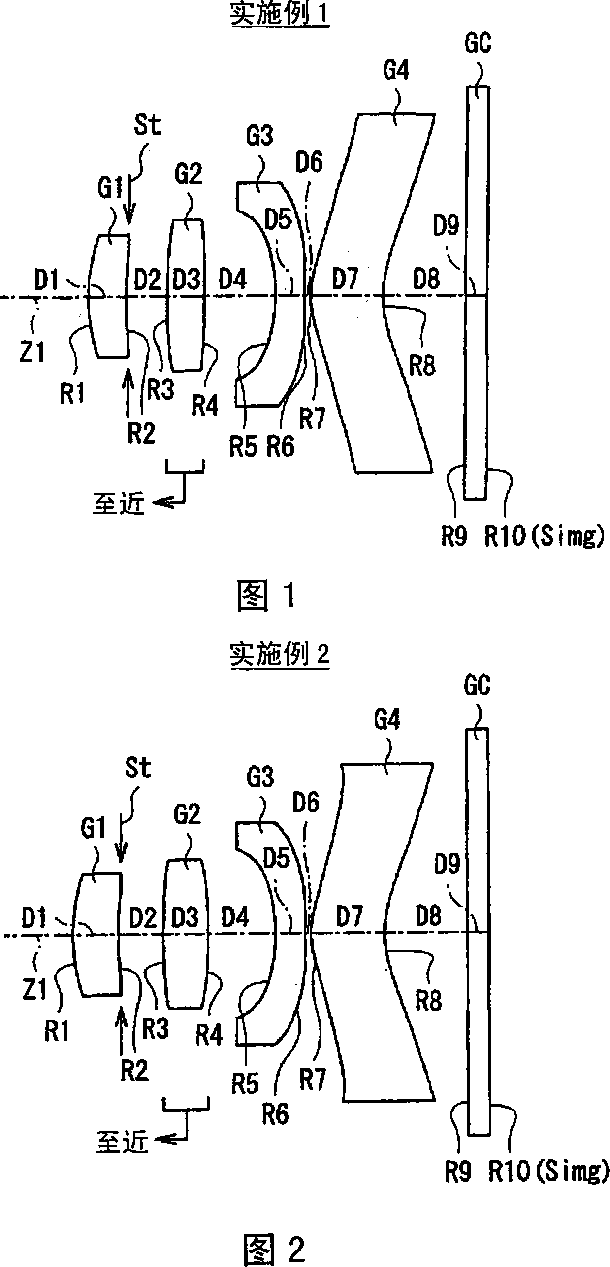
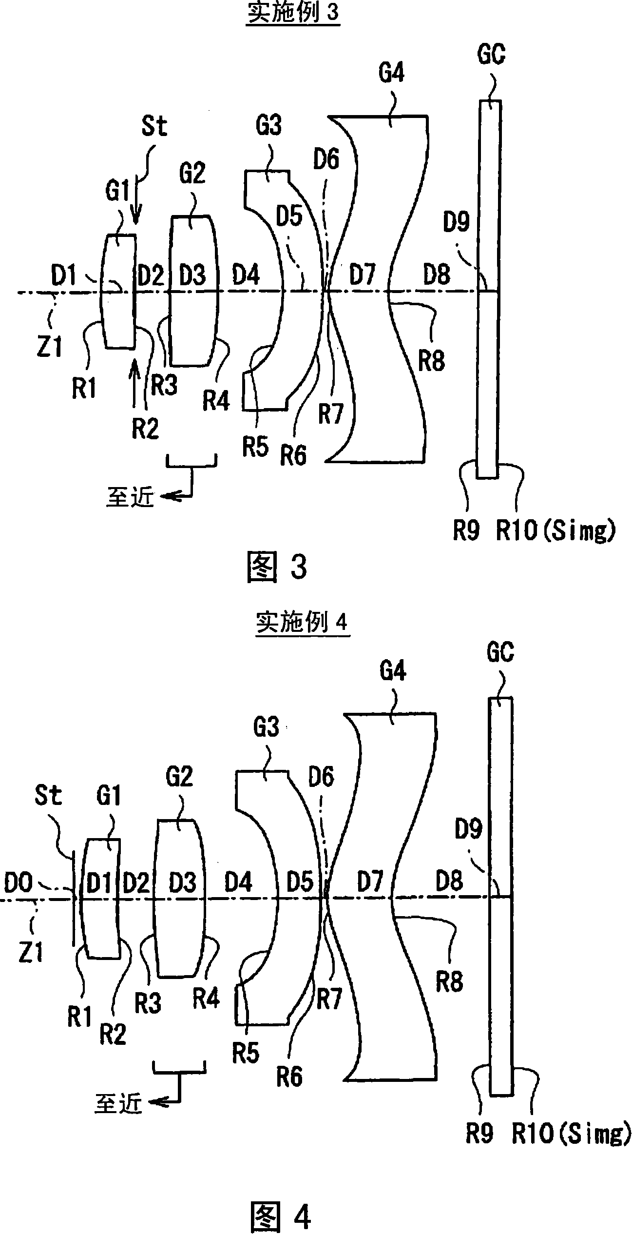
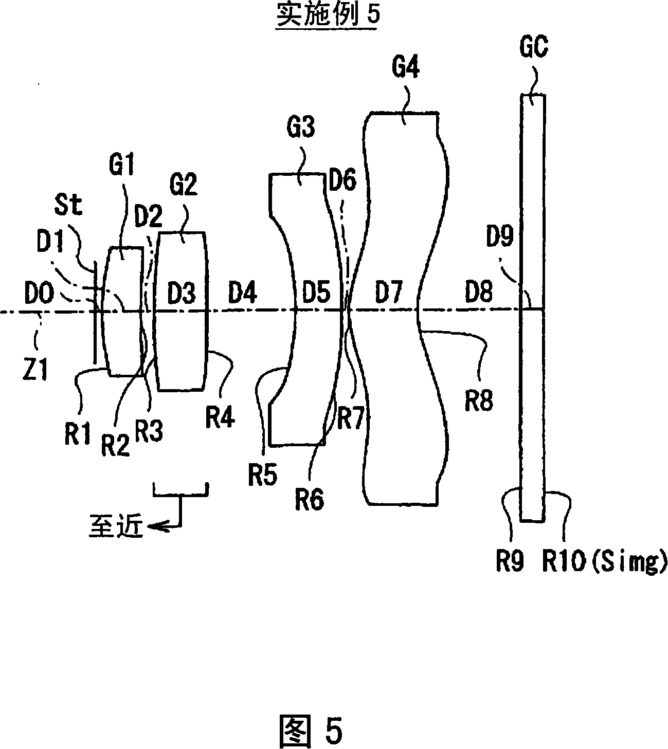
[0075]In the imaging lens according to Example 1, both surfaces of each lens are formed in an aspherical shape. In the basic lens data of FIG. 6(A), the numerical value of the radius of curvature near the optical axis is shown as the radius of curvature of these aspherical surfaces. In FIG. 6(B), the numerical value expressed as aspheric surface data, the symbol "E" indicates that the subsequent numerical value is "power exponent" with base 10, and indicates that the numerical value expressed by the exponential function with base 10 is the same as " E" is multiplied by the previous values. For example, when it is "1.0E-02", it means "1.0×10 -2 ".

[0076] Each coefficient A in the formula of the aspheric surface shape represented by the following formula (A) is entered as aspheric surface data N , the value of K. In more detail, Z represents the length (mm ). In the imaging lens according to Example 1, coefficients A of the 3rd to 10th orders are effectively used in addi...


PUM


Abstract

The invention provides an imaging lens for a single focus lens with a relatively small lens quantity, with the advantages of good focus adjustment property with the same length, small and good performance. Beginning from the object side, the imaging lens comprises a first lens (G1) having a negative reflective force whose side near the object side takes a concave side; and a forth lens (G4) whose shape near the optical axle takes a positive crescent shape with the convex side towards to the object side. The first lens (G1) is set as a front group; the third lens (G3) and the forth lens (G4) are set as a rear group; and the second lens (G2) is used as the focus lens; and the second lens (G2) is moved on the optical axle for focusing and adjustment. As a focusing lens, the invention satisfies the following conditional expression: 1.0 is less than FL / f which is less than 5.0 and so on, wherein, (X)f is the focus of the whole system and FL is the focus of the focusing lens.

Description

technical field [0001] The present invention relates to a kind of imaging equipment using imaging elements such as CCD (Charge Coupled Device) or CMOS (Complementary Metal Oxide Semiconductor), such as digital still cameras, mobile phones with cameras, and information mobile terminals (PDA: personal digital assistant) and other imaging lenses, especially imaging lenses capable of focus adjustment using a single focus lens. Background technique [0002] In recent years, the miniaturization and high pixelation of imaging elements such as CCD and CMOS are progressing. Therefore, the main body of the imaging device and the lens mounted thereon are also required to be compact and high performance. Conventionally, for example, an imaging lens mounted on a mobile phone with a camera is often composed of three lenses. However, the number of lenses tends to increase further in order to cope with higher pixel count. Patent Document 1 discloses single-focus imaging lenses with 4-elem...

Claims


Application Information

Patent Timeline
Patent Type & Authority Applications(China)
IPC IPC(8): G02B13/00G02B9/10
CPCG02B9/34G02B13/004G02B9/60G02B3/00
Inventor 佐藤贤一
Owner TIANJIN OFILM OPTO ELECTRONICS CO LTD
Learn More