A device and method for acquiring positioning images of basic parts in slm composite manufacturing
What is Al technical title?
Al technical title is built by PatSnap Al team. It summarizes the technical point description of the patent document.
A positioning image and acquisition device technology, which is applied in the field of SLM composite manufacturing basic parts positioning image acquisition device, can solve the problems of increased molding time and processing cost, difficult blade part molding, long processing time, etc., and achieve light weight and stable image , the effect of convenient adjustment of focal length
Active Publication Date: 2022-06-28
ZHONGBEI UNIV
View PDF11 Cites 0 Cited by
Summary
Abstract
Description
Claims
Application Information
AI Technical Summary
This helps you quickly interpret patents by identifying the three key elements:
Problems solved by technology
Method used
Benefits of technology
Problems solved by technology
This technology uses a high-energy-density laser beam to rapidly melt and solidify metal powder to form parts with complete metallurgical bonding and close to 100% density; this technology can form components with arbitrary complex structures, but compared with traditional machining, processing Long time and high processing cost
[0003] Some parts have both a simple structure and a complex structure; for example, the impeller has both a simple structure-a solid disc-shaped part and a complex structure-the blade part; if it is fully processed by traditional machining, the blade part is difficult to form and easy to deform , The processing cost is high; if SLM technology is fully used, the molding time and processing cost will be greatly increased; if the part is divided into two, the solid disc-shaped part is formed by traditional machining, and then the blade structure is formed by SLM on the solid disc-shaped part , which can realize high-efficiency and low-cost processing of parts
Method used
Image
Click on the blue label to locate the original text in one second.
Reading with bidirectional positioning of images and text.
Examples
Embodiment Construction
[0048] The specific embodiments of the present invention will be further described below with reference to the accompanying drawings.
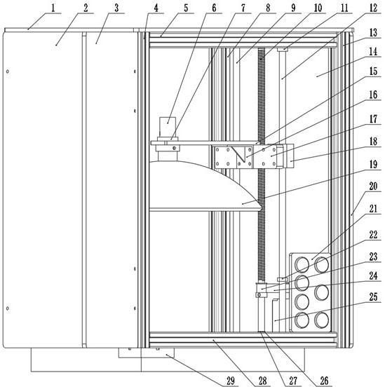
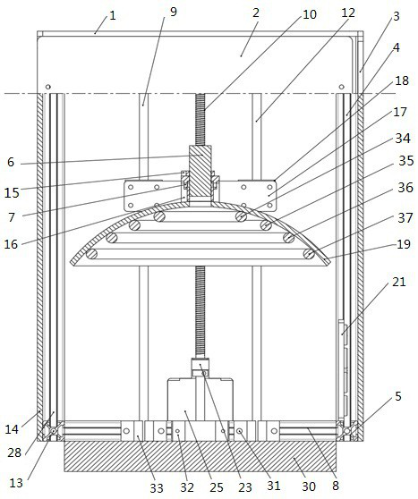
[0049] The device and method of the embodiments of the present invention are mainly proposed for the following image acquisition equipment: image acquisition to solve the problem that the positions of the SLM molding chamber, the machining base, and the substrate cannot be determined when the laser selective melting technology and traditional machining are combined to form components The device is suitable for the most widely used SLM equipment in the market with a molding size of 250*250.
[0050] An image acquisition device for positioning basic parts of SLM composite manufacturing, comprising a support module, a transmission module, an image acquisition module, an image processing module, and a control module; the support module can support the transmission module, the image acquisition module, and the control module; the transmission module...
PUM
Abstract
The present invention relates to the field of advanced manufacturing and intelligent equipment, and in particular to a positioning image acquisition device for SLM manufacturing basic parts, including a frame rod, a guide rod support seat, a screw support seat, an industrial camera support plate, and a box-type linear slider bearing guide rod , high-precision motors, ring LED lights, industrial cameras, light baffles and controllers, etc.; high-precision motors, shock-absorbing rubber pads and high-precision motor brackets are connected by screws, and the timing belt pulley on the high-precision motors is connected by the timing belt and the screw The synchronous pulley is connected, the box-type linear slider bearing guide rod 2 is installed on the box-type linear slider bearing 1, the industrial camera is connected with the light stand, the industrial camera support plate, and the camera fixing part, and the light stand is supported by the jack wire and the industrial camera board connection, the device is portable, easy to install, and light in weight; it can be used in current general-purpose SLM equipment; it adopts a one-way light-transmitting board, which does not receive external light interference, and the image is stable; the system light source and focal length are easy to adjust, and the collected image is clear.
Description
technical field [0001] The invention relates to contour image recognition and coordinate extraction of basic parts of forming bins of selective laser melting (SLM) forming equipment, in particular to a positioning image acquisition device and method of SLM composite manufacturing basic parts. Background technique [0002] Traditional machining has the advantages of fast processing speed and low cost, but it cannot process complex special structures and cannot meet the individual requirements of customers for workpieces. Selective Laser Melting (SLM) is one of the most promising technologies in the field of additive manufacturing (also known as 3D printing). This technology uses a high-energy-density laser beam to rapidly melt and solidify metal powder, forming parts with complete metallurgical bonding and a density close to 100%; this technology can form components with any complex structure, but compared with traditional machining, machining Long time and high processing c...
Claims
Application Information
Patent Timeline
Application Date:The date an application was filed.
Publication Date:The date a patent or application was officially published.
First Publication Date:The earliest publication date of a patent with the same application number.
Issue Date:Publication date of the patent grant document.
PCT Entry Date:The Entry date of PCT National Phase.
Estimated Expiry Date:The statutory expiry date of a patent right according to the Patent Law, and it is the longest term of protection that the patent right can achieve without the termination of the patent right due to other reasons(Term extension factor has been taken into account ).
Invalid Date:Actual expiry date is based on effective date or publication date of legal transaction data of invalid patent.