
Imaging apparatus

a technology of imaging apparatus and spherical lens, which is applied in the field of imaging apparatus, can solve the problems of increasing manufacturing difficulty and difficulty in changing the angle of view

Active Publication Date: 2020-09-17
FUJIFILM CORP
View PDF0 Cites 0 Cited by
  • Summary
  • Abstract
  • Description
  • Claims
  • Application Information

AI Technical Summary

Benefits of technology

This patent describes a technology that allows for easy focus adjustment after motion picture imaging. The technology uses a lensless camera with a Fresnel zone plate and image sensor. When changing the angle of view, the pitch of the Fresnel zone plate needs to be adjusted, which can lead to decrease in optical resolution or increase in manufacturing difficulty. The patent aims to address these issues and improve the technology.

Problems solved by technology

In the case of (3), the pitch needs to be decreased, and thus, the level of difficulty in manufacturing is increased.
In the technology of the related art, it is difficult to change the angle of view while maintaining a refocusing function in the imaging apparatus including the coded aperture.

Method used


Image

  • Imaging apparatus
  • Imaging apparatus
  • Imaging apparatus

Examples


example 1

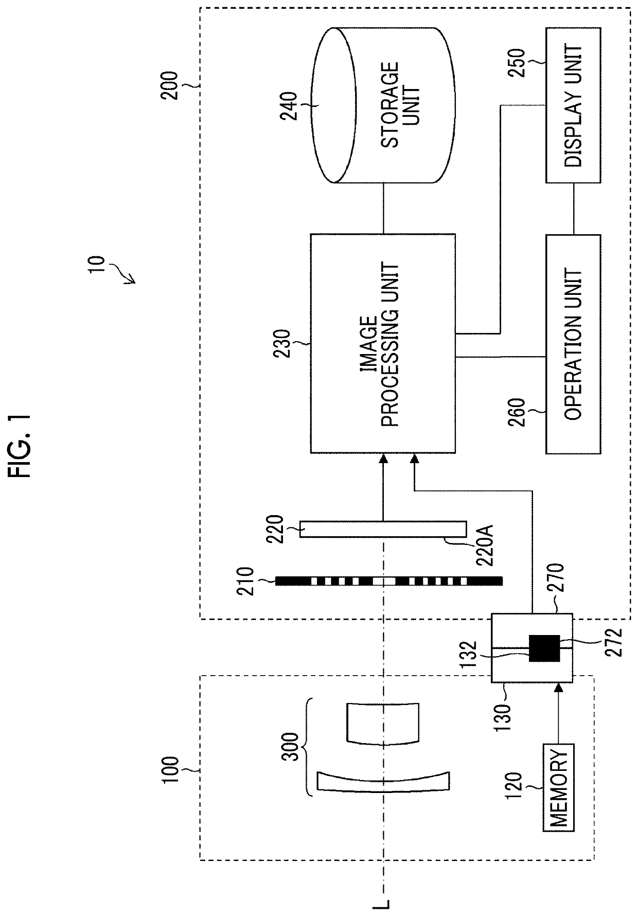
[0059]FIG. 6A is a diagram illustrating arrangement of the lens 300, the Fresnel zone plate 210, and the imaging surface 220A of the imaging element 220. The lens 300 is a wide conversion lens composed of a front group 310 having a negative power (refractive power; the same applies hereinafter) and a rear group 320 having a positive power in order from the object side (subject side) and is composed of lenses 302, 304, 306, and 308. The Fresnel zone plate 210 is arranged at the position of a pupil (position of a stop) of the lens 300.

example 2

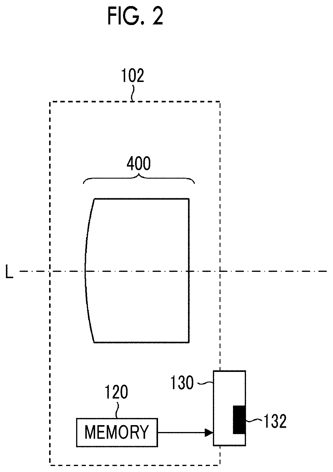
[0060]FIG. 6B is a diagram illustrating arrangement of the lens 400, the Fresnel zone plate 210, and the imaging surface 220A of the imaging element 220. The lens 400 is a tele conversion lens and is composed of lenses 402, 404, 406, and 408. The Fresnel zone plate 210 is arranged at the position of a pupil (position of a stop) of the lens 400.

[0061]The angles of view of the lenses 300 and 400 are fixed. However, the lens attached to the imaging apparatus main body in the imaging apparatus according to the embodiment of the present invention may be a zoom lens capable of changing the angle of view (focal length).

Optical Path Diagram

[0062]FIG. 7A is a diagram illustrating the optical paths of an axial luminous flux B1 and a luminous flux B2 having the maximum angle of view with respect to the lens 300 in a state where an ideal lens I1 (lens having zero aberration) is arranged at the position of the pupil of the lens 300. In actuality, the Fresnel zone plate 210 is arranged at the pos...

first embodiment

Effect of First Embodiment

[0100]As described above, the imaging apparatus 10 according to the first embodiment has the refocusing function provided by the coded aperture and can change the angle of view.

Other Aspects

[0101]In the first embodiment, the complex image is generated by multiplying the projected image with the first and second Fresnel zone patterns, and the image of the spatial domain is reconstructed by performing complex Fourier transformation on the complex image. However, the reconstruction of the image in the imaging apparatus according to the embodiment of the present invention is not limited to an aspect of using the complex image. As described above for Expressions (6), (8), and (10) and the like, the multiplied image may be obtained by multiplying the projected image with a real number function such as Mr(r), and the image may be reconstructed by performing Fourier transformation on the multiplied image. In this case, an overlap of the subject image occurs in the ...


PUM


Abstract

An object of the present invention is provide a coded aperture imaging apparatus that has a refocusing function and can change an angle of view. An imaging apparatus includes an imaging apparatus main body including a coded aperture, an imaging element that outputs a signal indicating a projected image of a subject, and an image restoration unit that reconstructs an image of a spatial domain based on the signal, and a lens attached to the imaging apparatus main body on a subject side from the coded aperture and changes an imaging angle of view in a state where the lens is attached to the imaging apparatus main body with respect to an imaging angle of view in a state where the lens is not attached to the imaging apparatus main body, in which the projected image is formed on the imaging element by the lens and the coded aperture.

Description

CROSS-REFERENCE TO RELATED APPLICATIONS[0001]This application is a Continuation of PCT International Application No. PCT / JP2018 / 046789 filed on Dec. 19, 2018, which claims priority under 35 U.S.C § 119(a) to Japanese Patent Application No. 2017-249069 filed on Dec. 26, 2017. Each of the above application(s) is hereby expressly incorporated by reference, in its entirety, into the present application.BACKGROUND OF THE INVENTION1. Field of the Invention[0002]The present invention relates to an imaging apparatus comprising a coded aperture.2. Description of the Related Art[0003]In recent years, technologies for acquiring an image of a subject without a lens have been developed. For example, in “Development of lensless camera technology enabling easy focus adjustment after motion picture imaging”, [online], Nov. 15, 2016, Hitachi, Ltd., [searched on May 8, 2017], Internet (http: / / www.hitachi.co.jp / New / cnews / month / 2016 / 11 / 1115.html), a Fresnel zone plate is arranged near an imaging elemen...

Claims


Application Information

Patent Timeline
Patent Type & Authority Applications(United States)
IPC IPC(8): G06T5/00G03B17/14G06T5/10
CPCG06T5/006G06T5/10G03B17/14G02B15/10G02B15/12H04N23/957H04N23/60G06T5/80
Inventor KISHINE, YASUNOBUKOMATSU, DAIKI
Owner FUJIFILM CORP
Learn More