
Manufacturing method of back board of backlight module

A manufacturing method and backlight module technology, applied in the fields of optics, nonlinear optics, components of lighting devices, etc.

Active Publication Date: 2012-04-18
AU OPTRONICS CORP
View PDF2 Cites 0 Cited by
  • Summary
  • Abstract
  • Description
  • Claims
  • Application Information

AI Technical Summary

Problems solved by technology

[0006] The present invention provides a backboard to solve the problem of holes in the traditional backboard due to the formation of hooks

Method used


Image

  • Manufacturing method of back board of backlight module
  • Manufacturing method of back board of backlight module
  • Manufacturing method of back board of backlight module

Examples


Embodiment Construction

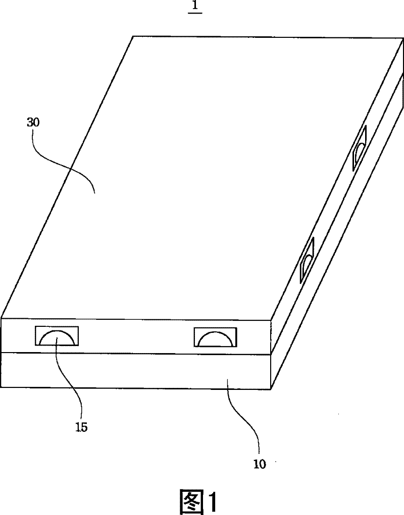
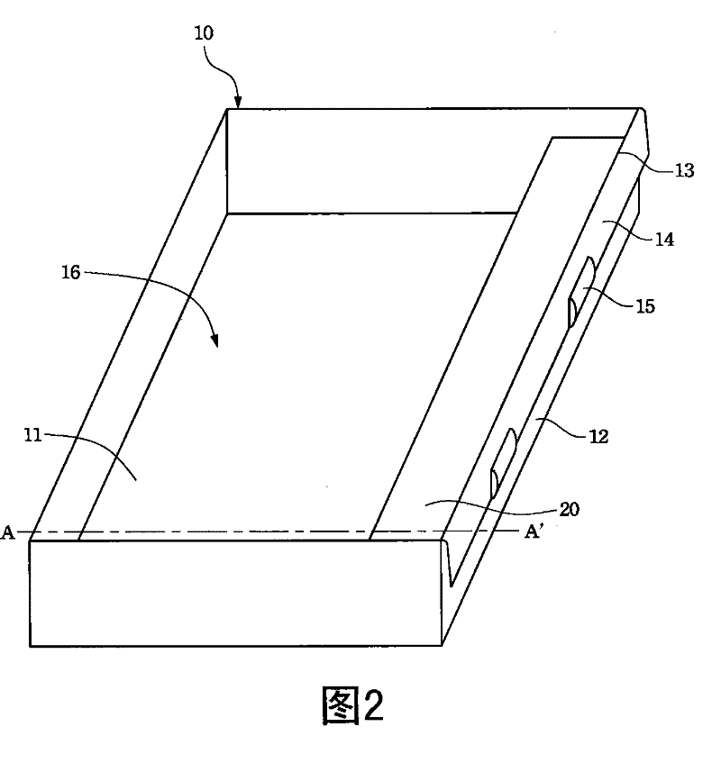
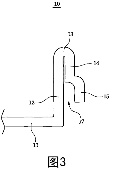
[0032] image 3 for figure 1 A side view of the backplane 10. like image 3 As shown, the engaging portion 15 can extend away from the inner portion 12, that is, the engaging portion 15 can protrude outward to engage figure 1 The upper frame 30 and the backplane 10. more specifically, image 3 The engaging portion 15 can have a groove 17 on its side facing away from the curved portion 13, so as to be manufactured by stamping technology. It should be understood that the above-mentioned shape of the engaging portion 15 is for illustration only, and is not intended to limit the present invention. As long as the upper frame and the back panel can be engaged, the engaging portion can also have other appropriate shapes.

[0033] for example, Figure 4 Although the engaging portion 15 protrudes from the surface of the reflex portion 14 and also has a groove 17, it is different from image 3 Yes, Figure 4 The bottom of the engaging portion 15 is folded toward the inner port...


PUM


Abstract

A back board comprises an inner side part, a bottom part, a reflection part, a bending part and a block part, wherein the bottom part and the inner side part are connected to form a capacity space. The reflective part and the inner side part are face to face, and the inner side part is connected with the reflective part through the bending part. The block part is arranged on the reflection part. The invention also relates to a manufacturing method of a back board. As the back board of the invention does not retain a broken hole at an inner side part, the dust does not enter the backlight module inside from the broken hole. In addition, the invention keeps flat at the inner side part of the back board, so the problems resulted from light beam leakage are also solved.

Description

technical field [0001] The present invention relates to a backlight module, in particular to a structural component of the backlight module, that is, a backplane of the backlight module and a manufacturing method thereof. Background technique [0002] Liquid crystal display is mainly composed of color filter, backlight module, drive circuit, optical film, glass substrate and other parts. Since the liquid crystal panel itself does not have light-emitting characteristics, the display function must be achieved through the backlight module. [0003] The existing backlight module includes a backplane and an upper frame, and the backplane and the upper frame are combined to form an accommodating space for placing light sources and optical elements. In this way, the light source can be properly combined with the display, and the light source path can be provided and efficiently transmitted to the display area. [0004] The existing backboard and upper frame combination method is ...

Claims


Application Information

Patent Timeline
Patent Type & Authority Patents(China)
IPC IPC(8): G02F1/13357G02F1/1333F21V21/00
Inventor 游家欣
Owner AU OPTRONICS CORP
Learn More