Chain transmission device

A technology of chain drive and chain, which is applied in the direction of transmission device, transmission chain, belt/chain/gear, etc. It can solve the problems of reduced strength, large extension of connecting pins, and large noise, etc., and achieves suppression of wear extension, wear suppression, and noise suppression Effect

Active Publication Date: 2008-04-23
TSUBAKIMOTO CHAIN CO
View PDF1 Cites 6 Cited by
  • Summary
  • Abstract
  • Description
  • Claims
  • Application Information

AI Technical Summary

Problems solved by technology

[0006] Using the aforementioned known silent chain chain drive, the silent chain is advantageous in terms of higher strength and lower noise than the roller chain, but on the contrary, there is a problem that the spread due to the wear of the connecting pin is larger than that of the roller chain, The chain drive using the known roller chain, the roller chain is superior in fatigue resistance, wear resistance and extension, on the contrary, the high strength of the roller becomes the bottleneck and the high strength of the chain is difficult, and it exists compared to the silent chain The problem of high noise when the sprocket is engaged
[0007] In addition, in the above-mentioned conventional compound chain transmission device, since the two outer tooth sides of the chain plate teeth of the silent chain are in contact with the sprocket teeth, there is a problem as follows: The bending movement of the chain plate when it is about to disengage, the fit of the connecting pin pressed and fixed in the pin hole of the outermost chain plate is loosened, the pin hole and the connecting pin are worn, and the wear and tear of the chain is promoted, and the strength is reduced.
In addition, since four chain plates with teeth and four chain plates without teeth are arranged in the width direction of the composite chain, a total of eight, there is a problem that the weight of the chain itself is increased and the cost is high.

Method used


Image

  • Chain transmission device
  • Chain transmission device
  • Chain transmission device

Examples


Embodiment Construction

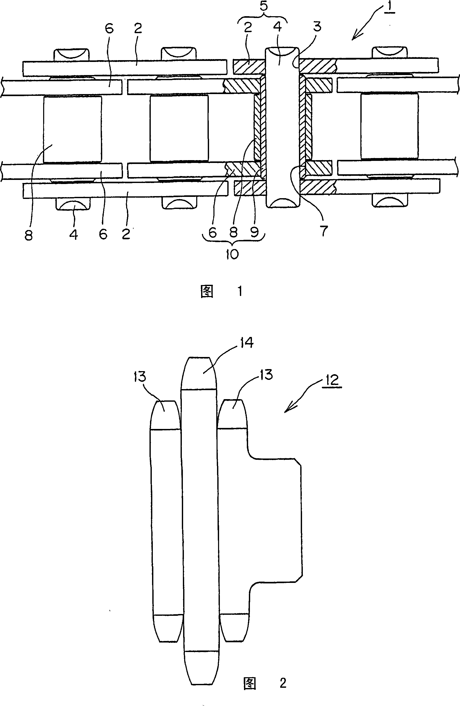
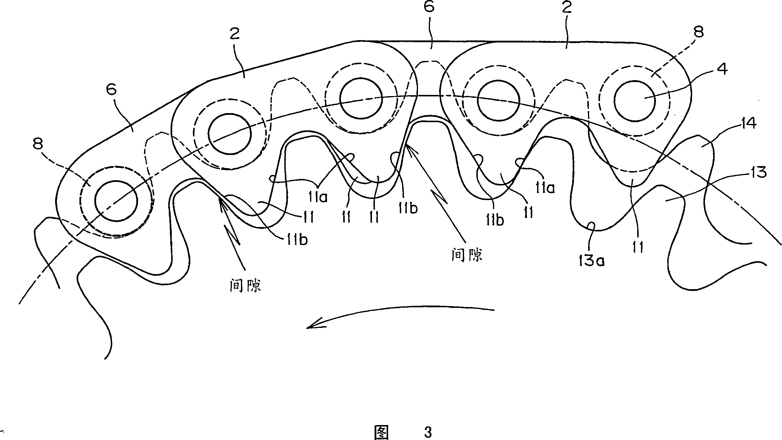
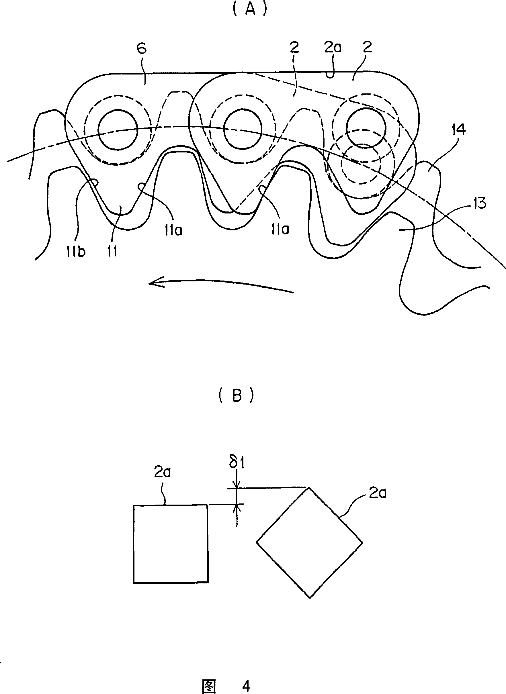
[0042] Embodiment 1 of the present invention will be described with reference to FIGS. 1 to 4 . Fig. 1 is a partial plan view showing the main part of the chain used in the chain transmission device in Embodiment 1 of the present invention in cross section, Fig. 2 is a front view of a sprocket, Fig. 3 is an explanatory diagram of the meshing state of the chain, and Fig. (A) is an explanatory diagram of the meshing operation of the link plates, and (B) is an explanatory diagram schematically showing the polygonal motion of the chain.

[0043] This Embodiment 1 chain transmission (not shown) consists of a chain and a sprocket, and the chain has a plurality of chain plates having a pair of teeth and rollers.

[0044] As shown in Figure 1, the chain 1 includes: the outer chain link 5 that inserts the two ends of the connecting pin 4 and is fixed in the pin hole 3 of a pair of outer chain plates 2; The sleeve 9 is embedded and fixed in the inner chain link 10 in the sleeve hole 7 ...


PUM


Abstract

The invention provides a chain transmission, which exhibits the advantages of a silent chain as well as those of a roller chain, which can avoid wear elongation and reduction of strength, and which also achieves noise reduction and weight reduction. A hybrid chain comprises a chain having toothed link plates 2, 6, located on either sides of bushings 9, wherein the toothed link plates mesh 2, 6, with first 13 and second sets 13 of teeth on a sprocket while the bushings 9 engage a third set 14 of teeth on the sprocket located between the first and second sets. The bushings ideally have rollers 10 mounted thereon. When meshing with the sprocket, a rear flank 11a of a tooth of a link plate 2, 6 engages the forward flank of a sprocket tooth 13. Once the rollers / bushings 8 become seated between the teeth of the third set 14, the flank of the link plate is spaced away (clearance) from the sprocket tooth. Each link plate may have a single tooth, or possibly two teeth. All sets of teeth of the sprocket may have the same angular pitch, with the middle set shifted by half the pitch angle.

Description

technical field [0001] The present invention relates to a chain transmission device that transmits power by a chain wound around a sprocket, for example, to a chain transmission device suitable for driving a driven shaft of an auxiliary machine such as a valve train of a four-cycle engine or an oil pump, and particularly, It relates to a chain transmission including a chain and a sprocket using a link plate having a pair of tooth portions generally used in a silent chain instead of a link plate without a tooth portion constituting a roller chain. Background technique [0002] A chain drive using a silent chain is known, and a chain such as a bush chain or a roller chain is used. In addition, conventionally, there has been known a compound chain transmission including a compound chain in which links of a silent chain and a roller chain are combined, and a sprocket having teeth meshing with these links (refer to Patent Document 1). [0003] As shown in FIG. 7 , the composite...

Claims


Application Information

Patent Timeline
Patent Type & Authority Applications(China)
IPC IPC(8): F16H7/06F16G13/04
CPCF16H7/06F16H55/30F16G13/04F16G13/06F16G13/02
Inventor 黑畑纯也
Owner TSUBAKIMOTO CHAIN CO
Why Eureka
Try Eureka