
Conversion device for RF remote distribution system in communication system

A conversion device and radio frequency remote technology, which is applied in the field of wireless communication, can solve the problems of cost increase and high price, and achieve the effects of reducing networking cost, design complexity and cost

Inactive Publication Date: 2008-04-23
ZTE CORP
View PDF0 Cites 26 Cited by
  • Summary
  • Abstract
  • Description
  • Claims
  • Application Information

AI Technical Summary

Problems solved by technology

Due to the relatively high price of photoelectric converters, both the RRU / remote unit and the BBU / near-end unit have a large number of photoelectric converters, which will greatly increase the cost

Method used


Image

  • Conversion device for RF remote distribution system in communication system
  • Conversion device for RF remote distribution system in communication system
  • Conversion device for RF remote distribution system in communication system

Examples


Embodiment Construction

[0024] Below in conjunction with accompanying drawing, the present invention will be described in further detail:

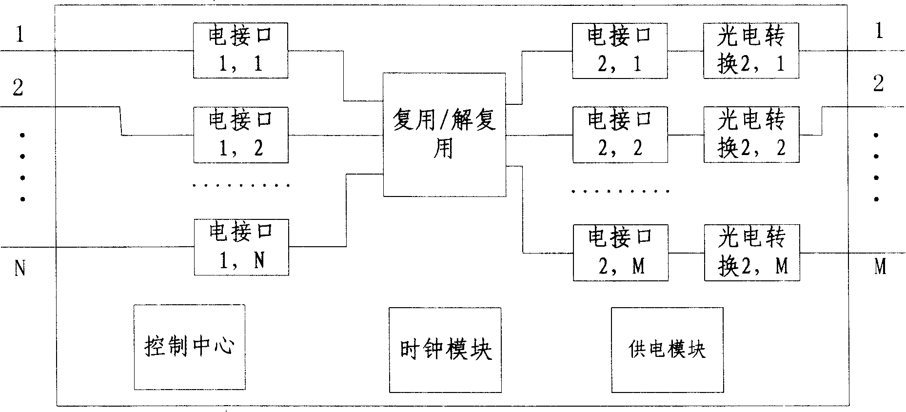
[0025] The conversion device described in the present invention is used to complete the interface conversion between the radio frequency remote end and the baseband pool / base station / near end machine, see figure 2 . The radio remote here can be the remote radio in the remote radio system, or the remote unit in the digital optical fiber repeater. The figure shows the situation when a conversion device is added between a remote radio frequency and a baseband pool / base station / near end. The communication between the remote radio frequency and the conversion device is through electrical signals; the communication between the baseband pool / base station / near-end machine and the conversion device is through electrical signals or optical signals. The interfaces on both sides of the conversion device may also have multiple remote radio frequencies and multiple baseband...


PUM


Abstract

This invention discloses a converting device used in a RF remote distribution system in the communication system including: a converting module with the interface of one end connected with a set of RF remote or an upper level converting device and the interface of another end connected with another set of back stage converting device or baseband pool / base station / near end device, a control center monitoring upper / lower level modules and alarming, a clock module guaranteeing unity of clocks of the modules and a supply module guaranteeing normal work of the modules.

Description

technical field [0001] The invention relates to a conversion device used in a radio frequency remote distribution system, in particular to 2G and 3G (second generation and third generation wireless communication systems) distributed coverage networks in the field of wireless communication. Background technique [0002] With the development of 3G technology, in order to solve the RF power loss caused by the feeder, there is a distributed solution of BBU (baseband pool) + RRU (radio remote unit). This solution usually connects the BBU and RRU through optical fibers. At present, there is a digital optical fiber repeater system in the repeater station, and the near-end unit and the far-end unit are also connected through optical fibers. For block diagrams of the two systems see figure 1 . [0003] When a BBU / near-end unit corresponds to a large number of RRUs / remote units, if the RRU / remote unit is directly connected to the BBU / near-end unit, the BBU / near-end unit is required...

Claims


Application Information

Patent Timeline
Patent Type & Authority Applications(China)
IPC IPC(8): H04B10/20H04B3/04H04W88/08
Inventor 周海涛廖娟
Owner ZTE CORP
Learn More