Heat exchanger for a motor vehicle

A technology for heat exchangers and automobiles, applied in heat exchange equipment, heat exchanger shells, indirect heat exchangers, etc.

Inactive Publication Date: 2008-04-23
BEHR GMBH & CO KG
View PDF3 Cites 5 Cited by
  • Summary
  • Abstract
  • Description
  • Claims
  • Application Information

AI Technical Summary

Problems solved by technology

However, this heat exchanger also has disadvantages, especially in terms of the load on the brazing area of ​​the outer tubes and tube sheets.

Method used


Image

  • Heat exchanger for a motor vehicle
  • Heat exchanger for a motor vehicle
  • Heat exchanger for a motor vehicle

Examples


Embodiment Construction

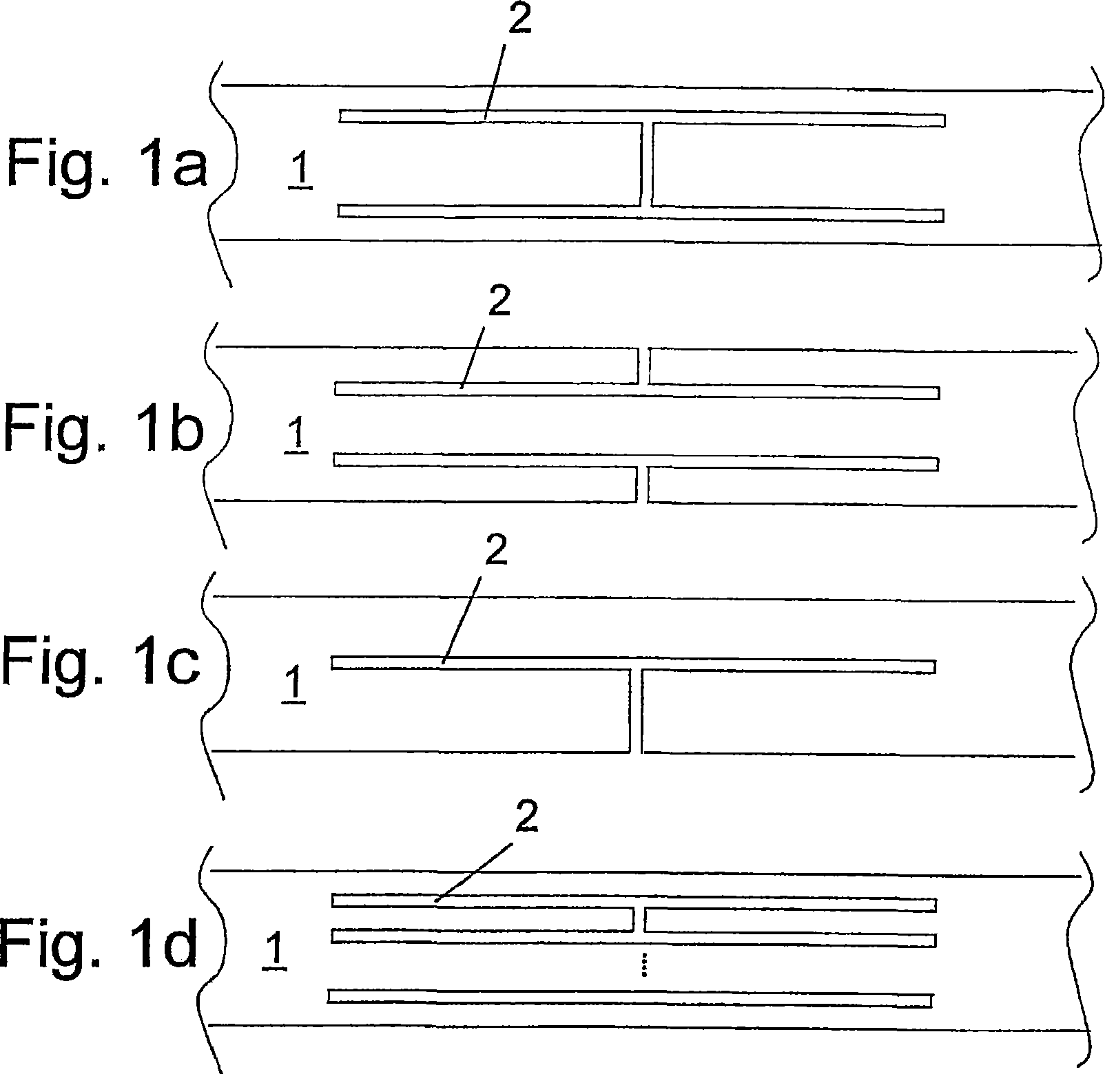
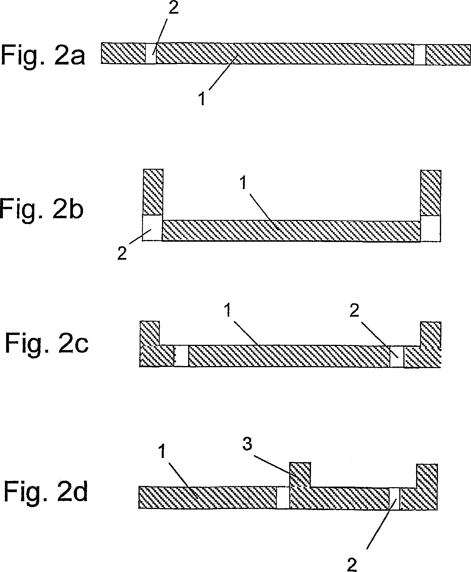
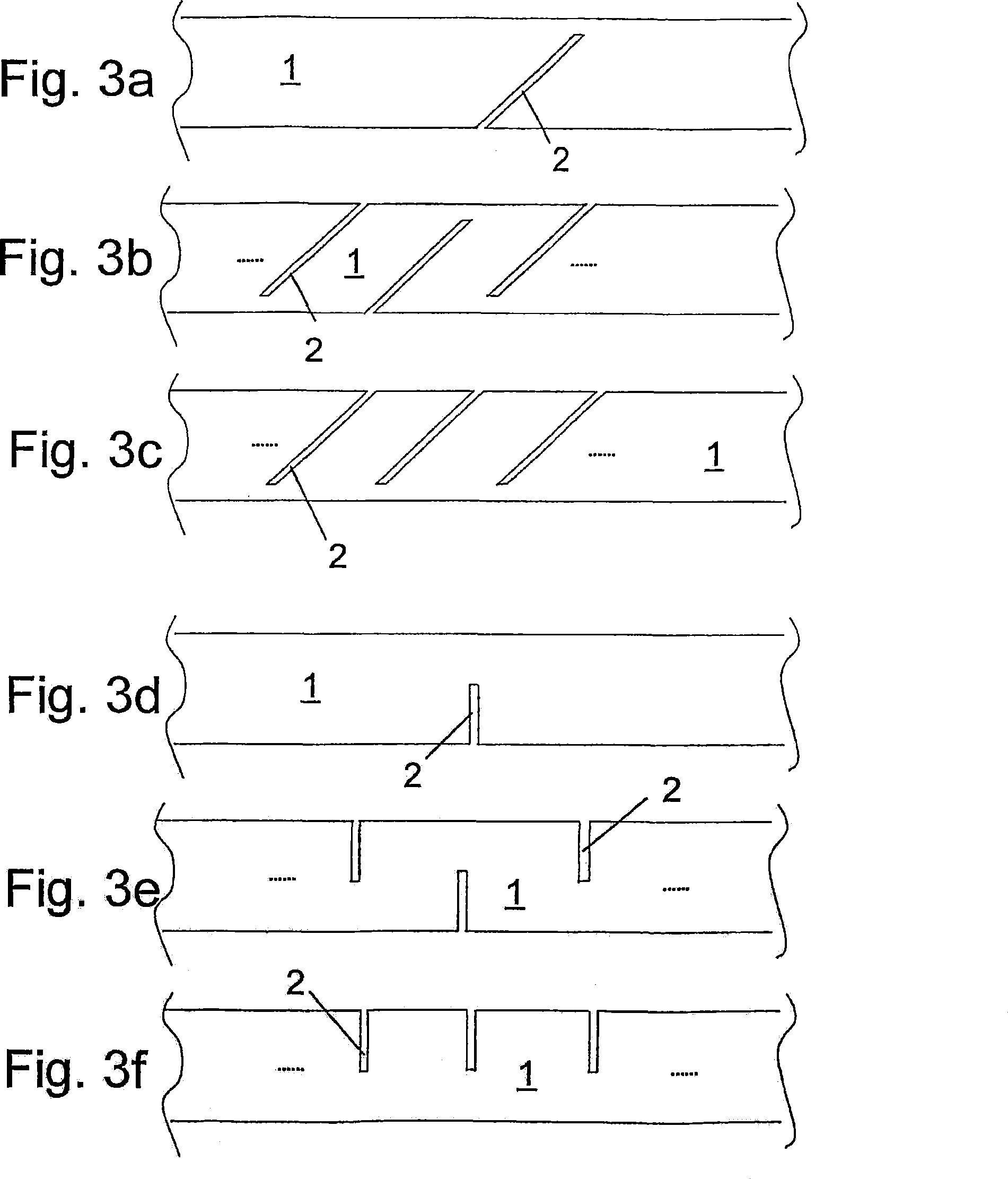
[0026] The heat exchanger, here the charge air cooler of the motor vehicle, only parts of the side plate 1 are shown in the figures. According to this embodiment, the heat exchanger has two collecting tanks formed by basin-shaped tank elements and tube sheets, a plurality of open tubes whose ends are inserted into the tube sheets, and corrugations arranged between the tubes. fins. The side plates 1 are arranged on the outside between the collecting tanks, for which purpose they are fixedly connected to the collecting tanks and not directly connected to tubes and / or corrugated fins. The individual parts of the heat exchanger are brazed to one another in a known manner, preferably in one brazing process, or are fixedly connected to one another in another way.

[0027] In order to keep the stresses between the tube plate and especially the outer tubes as low as possible at the start of operation or when the load on the charge air cooler starts to increase, corresponding springs ...


PUM


Abstract

The invention relates to a heat exchanger, in particular for a motor vehicle, having tubes and if appropriate corrugated fins through which a first, hot medium can flow and which are arranged between collecting boxes, and having at least one side part ( 1 ) which is arranged laterally between two collecting boxes, a second medium which flows around the tubes and if appropriate corrugated fins being colder than the first, hot medium during operation, the side part ( 1 ) absorbing at least some of the tensile stresses which act at least on the outermost tube as a result of different thermal expansions of the tubes and if appropriate corrugated fins, and the side part ( 1 ) having slots ( 2 ) and / or openings ( 4 ) which change the spring constant of the side part ( 1 ) in relation to a side part without slots and / or openings such that, in the event of a different longitudinal expansion of the central tubes relative to the outermost tube which is arranged adjacent to the side part ( 1 ), the tensile stress which acts on the outermost tube is reduced.

Description

technical field [0001] The invention relates to a heat exchanger, in particular for a motor vehicle, in particular to a charge air cooler according to the preamble of claim 1 . Background technique [0002] Heat exchangers generally have two collecting tanks, between which tubes such as flat tubes and corrugated fins are arranged. In order to connect the header boxes and protect the outer corrugated fins, side plates are often arranged between the header boxes. [0003] The problem is that on such heat exchangers, especially on charge air coolers, the outermost tubes are relatively cold compared to the middle tubes and the corresponding corrugated fins, so that during operation, especially At the start of operation, stresses are created in the heat exchanger due to temperature differences and the resulting differences in thermal expansion of the individual heat exchanger parts. Here, the outer tubes are cooler than the inner tubes and corrugated fins, ie they are shorter, ...

Claims


Application Information

Patent Timeline
Patent Type & Authority Applications(China)
IPC IPC(8): F28F9/00
CPCF28F9/001F28F2265/26F28D2021/0082
Inventor 迪特尔·巴赫纳
Owner BEHR GMBH & CO KG
Why Eureka
Try Eureka