Hydraulic forming equipment

A hydroforming and equipment technology, applied in the direction of mechanical equipment, fluid pressure converters, etc., can solve the problems of high power consumption, insensitive control of speed and start and stop, and affect the processing quality of pipe fittings, so as to ensure the quality of the liquid output Effect

Inactive Publication Date: 2008-04-30
庄添财
View PDF0 Cites 13 Cited by
  • Summary
  • Abstract
  • Description
  • Claims
  • Application Information

AI Technical Summary

Problems solved by technology

This supercharging device consumes a lot of power, and because the high and low pressure pumps are not very sensitive to the control of speed and start and stop, it affects the processing quality of pipe fittings

Method used


Image

  • Hydraulic forming equipment
  • Hydraulic forming equipment
  • Hydraulic forming equipment

Examples


Embodiment Construction

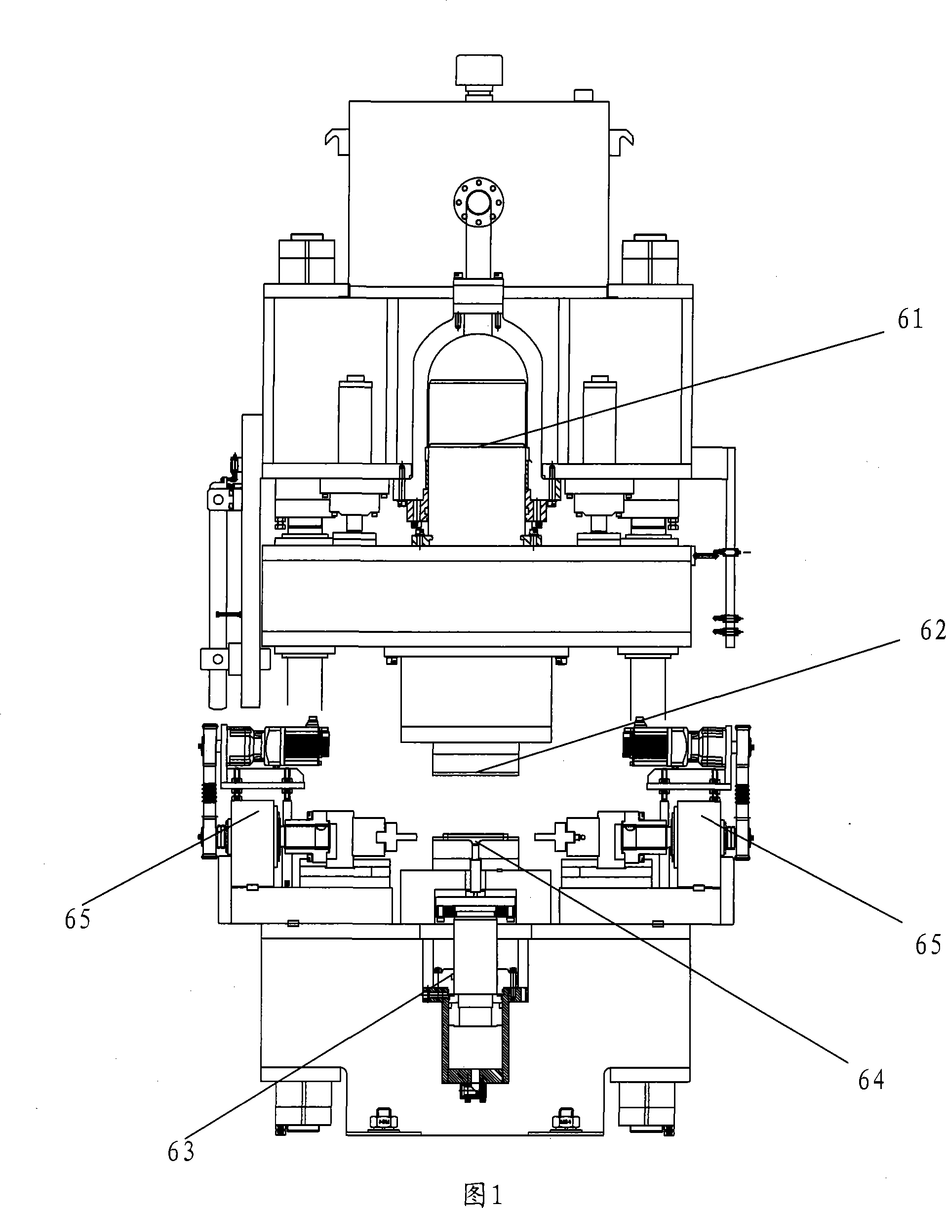
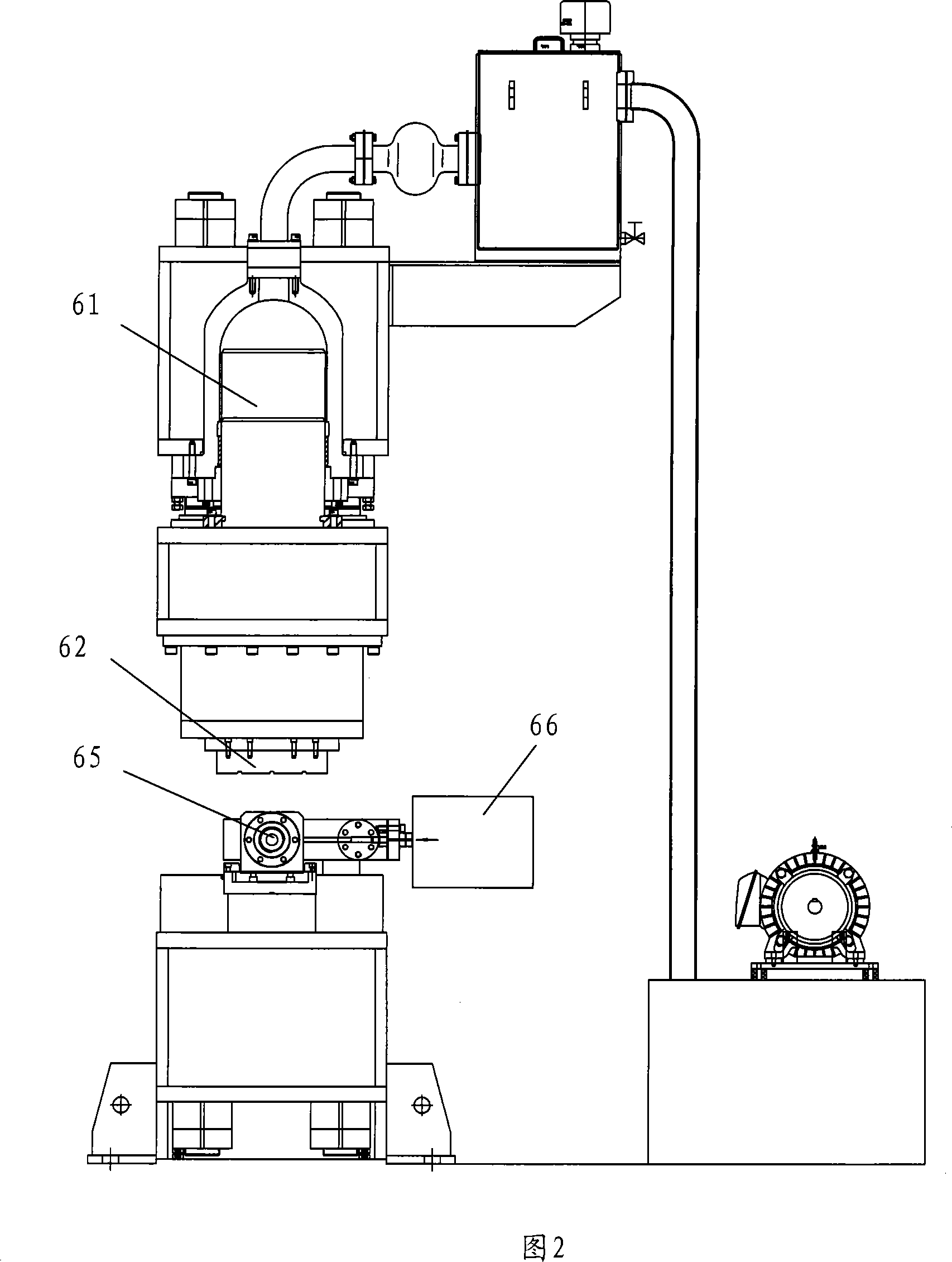
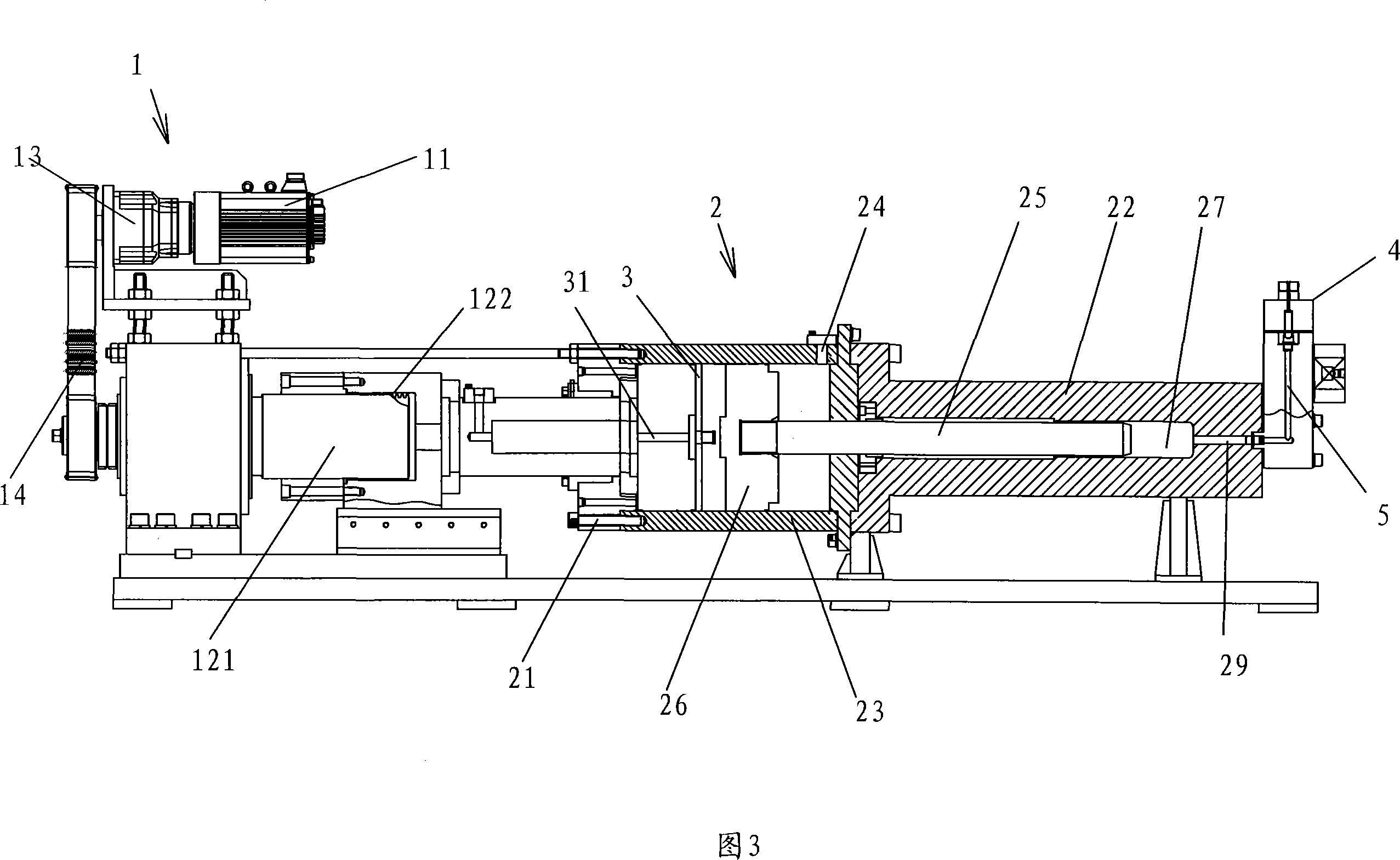
[0025] A hydroforming equipment, comprising a main pressure cylinder 61, a forming mold 62 arranged below the main pressure cylinder 61, a separate jacking cylinder 63 arranged below the forming mold 62, a workbench 64 arranged above the jacking cylinder 63, The thrust device 65 that is arranged on the two sides of workbench 64, is used for the supercharging device 66 that supplies liquid to workpiece, and supercharging device 66 comprises the supercharging mechanism 2 that is used for pressurizing low-pressure liquid to high-pressure liquid, is used for The driving mechanism 1 powered by the supercharging mechanism 2;

[0026] The supercharging mechanism 2 includes a first cylinder 22, a first piston 25 with one end slidably inserted inside the first cylinder 22, the first piston 25 is airtightly connected with the inner wall of the first cylinder 22, and the first piston 25 and part of the inner wall of the first cylinder to form a liquid storage chamber 27, the first cylind...


PUM


Abstract

A hydraulic molding device comprises a pressure unit utilized to supply liquid for processed units, the pressure unit comprises a pressure mechanism utilized to increase low-pressure liquid to high-pressure liquid and a driving mechanism which supplies power to the pressure mechanism, the pressure mechanism comprises a first cylinder, the first gas piston inserted in the inner portion of the first cylinder which is capable of sliding, the first gas piston is closely connected with the inner wall of the first cylinder, a liquid storage cavity is formed between the first gas piston and the partial inner wall of the first cylinder, an outlet is positioned on the first gas piston communicated with the liquid storage cavity, the cross-sectional area of the outlet is smaller than that of the liquid storage cavity, the first gas piston is in driving connection to the driving mechanism. The driving mechanism comprises a generator, bolts and cap nuts engaged with the bolts, wherein the optional one of the bolts and the cap nuts is in driving connection to the generator, and direction of movement of the other one is in driving connection to the first gas piston. The utility model is a pressure device with an automatic block system which is convenient to be controlled, and ensures the quality of work pieces in the fluid pressure manufacturing procedure.

Description

technical field [0001] The present invention designs a hydroforming equipment. Background technique [0002] The pressure boosting device in the existing hydroforming equipment uses a motor to drive the high and low pressure pumps to increase the pressure of the low pressure fluid, and the output high pressure fluid is pumped into the pipe fittings for pipe expansion. This supercharging device consumes a lot of power, and because the high and low pressure pumps are not very sensitive to the control of speed and start and stop, it affects the processing quality of the pipe fittings. Contents of the invention [0003] The object of the present invention is to provide a hydroforming equipment with a self-locking system and an easy-to-control booster device, which can well ensure the quality of workpieces during hydraulic processing. [0004] In order to achieve the above object, the technical scheme adopted in the present invention is: [0005] A hydroforming equipment, whi...

Claims


Application Information

Patent Timeline
Patent Type & Authority Applications(China)
IPC IPC(8): B21D26/02F15B3/00B21D26/033
Inventor 庄添财
Owner 庄添财
Why Eureka
Try Eureka