Pneumatic tire

A technology for pneumatic tires, new tires, applied in tire parts, tire tread/tread pattern, transportation and packaging, etc., can solve problems such as damage to belt layers, auxiliary belt layers, failures, etc., to improve traction performance , The effect of preventing stones from being trapped and inhibiting uneven wear

Inactive Publication Date: 2008-04-30
TOYO TIRE & RUBBER CO LTD
View PDF1 Cites 15 Cited by
  • Summary
  • Abstract
  • Description
  • Claims
  • Application Information

AI Technical Summary

Problems solved by technology

In addition, when a stone enters, it will damage the belt layer and the auxiliary belt layer, resulting in failure

Method used


Image

  • Pneumatic tire
  • Pneumatic tire
  • Pneumatic tire

Examples


Embodiment

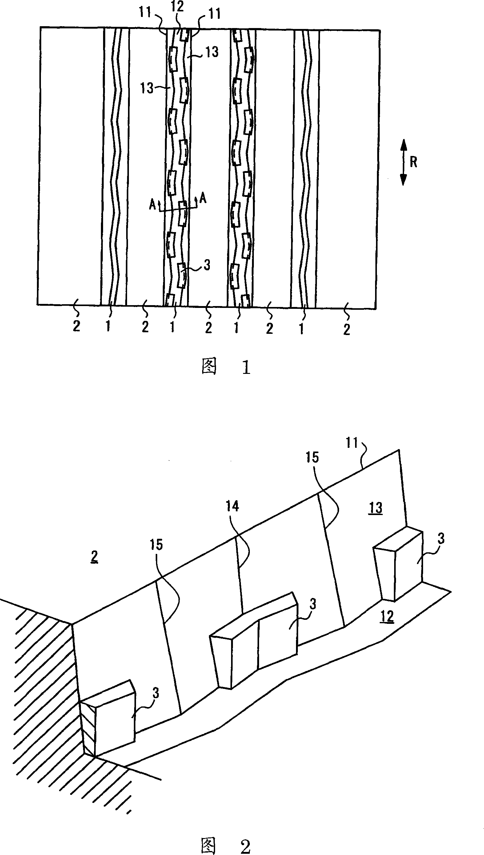
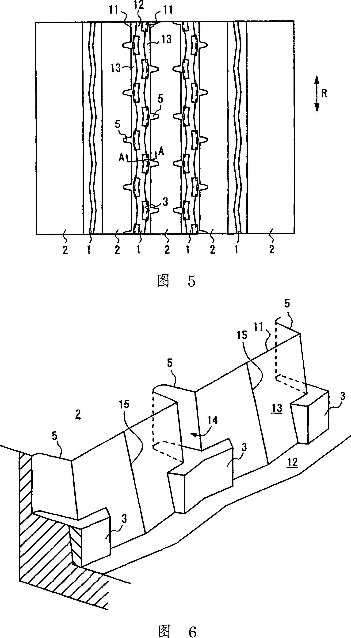
[0039] As an example, a pneumatic tire of the present invention was tested and mounted on a truck (axle structure 2-D) with a load of 10 tons for evaluation. In addition, the tread patterns of Examples 1 to 3 are the patterns shown in FIGS. 1 , 3 , and 5 , respectively. The depth D of the main groove 1 is 14.5 mm, the height H of the protrusion 3 is 3 mm, W, W1, and W2 in Figures 8 to 10 are 7 mm, 4.5 mm, and 6.5 mm, respectively, and L1, L2 are 23 mm, 17 mm, respectively. The width of shaped pattern 2 is 38mm. The length of the sipe 4 in embodiment 2 is 2.5 mm, the length of the notch 5 in embodiment 3 is 4 mm, and the width of the opening on the side wall 13 is 5.5 mm.

[0040] The tires of Conventional Examples 1 to 3 do not have protrusions having the same patterns as those of Examples 1 to 3. However, Conventional Example 2 has the same sipe as Example 2, and Conventional Example 3 has the same notches as Example 3. The tire of Conventional Example 4 has the same patte...


PUM


Abstract

In the pneumatic tire in which not less than three main grooves (1) extending in the tire circumferential direction R are formed and ribs (2) are formed by the main grooves (1), upper edges (11) of the main groove (1) when the tire is new extend in a linear manner in the tire circumferential direction (R), the bottom (12) of the main groove (1) extends in a zigzag manner in the tire circumferential direction (R), the sidewalls (13) of the main groove (1) is provided with concave portions and convex portions, and in the concave portion of at least one of the sidewalls (13) of the main groove (1), the protrusions (3) that is joined to the bottom (12) of the main groove (1) and to the sidewall (13). Further, the pneumatic tire may be provided with sipes or notches that extend from the concave portion to the inner side of the rib (2) in the tire width direction.

Description

technical field [0001] The present invention relates to a pneumatic tire. More specifically, it relates to a phenomenon called stone trapping which prevents stones from being caught in tire grooves while ensuring traction performance and drainage performance. Pneumatic tires produced. Background technique [0002] In order to obtain desired performance such as drainage performance, traction performance, and braking performance, the tread is engraved with main grooves extending in the tire circumferential direction and lateral grooves extending in the tire width direction. When stones are caught in the ditch and the stones cannot fall off, the stones will gradually enter toward the bottom of the ditch, sometimes damaging the bottom of the ditch. In addition, when a stone enters, the belt layer and the auxiliary belt layer are damaged, resulting in failure. In particular, the groove deformation of the main groove due to tire rolling is relatively small, so this tendency is s...

Claims


Application Information

Patent Timeline
Patent Type & Authority Applications(China)
IPC IPC(8): B60C11/13
CPCB60C11/047B60C11/045B60C2011/1338
Inventor 藤冈刚史
Owner TOYO TIRE & RUBBER CO LTD
Why Eureka
Try Eureka