
Storage device fixing mechanism

A storage device and fixing mechanism technology, applied in the direction of support structure installation, digital processing power distribution, etc., can solve the problems of increasing production cost and manufacturing, unable to reduce the number of parts, low gross profit rate, etc., to save the number of parts and improve the service life , cost-saving effect

Inactive Publication Date: 2008-04-30
INVENTEC CORP
View PDF0 Cites 11 Cited by
  • Summary
  • Abstract
  • Description
  • Claims
  • Application Information

AI Technical Summary

Problems solved by technology

[0010] Although the above-mentioned fixing mechanism provides a way to fix the storage device without using screws, if it is applied to the server host, the elastic element 130 is set upright on the outside of the chute 111b, because it still needs to be installed above the storage device. Therefore, the length of the elastic element 130 will be limited by the height of the storage device. Based on the principle of torque, the elastic element 130 whose length is limited will need to use a large force to push it away. Also because of this, for the elastic element The selection of 130 materials must use steel sheets or springs with better elasticity, which increases production costs and manufacturing difficulties
Furthermore, since the above-mentioned fixing mechanism must at least be provided with a long groove 111a and a sliding groove 111b on the positioning plate 111, as the purpose of positioning and fixing the storage device respectively, the total number of the front and rear fixing elements needs to be at least four. normal operation
Although the fixing mechanism can achieve the effect of tool-free disassembly and assembly, it cannot reduce the number of parts required
[0011] Because the mechanism design with simple structure and few parts can cope with the current competitive environment with low gross profit margin, how to develop a storage device fixing mechanism to solve the above-mentioned shortcomings of the prior art is an urgent problem to be solved today.

Method used


Image

  • Storage device fixing mechanism
  • Storage device fixing mechanism
  • Storage device fixing mechanism

Examples


Embodiment Construction

[0048] Embodiments of the present invention are described below through specific examples, and those skilled in the art can easily understand other advantages and effects of the present invention from the content disclosed in this specification.

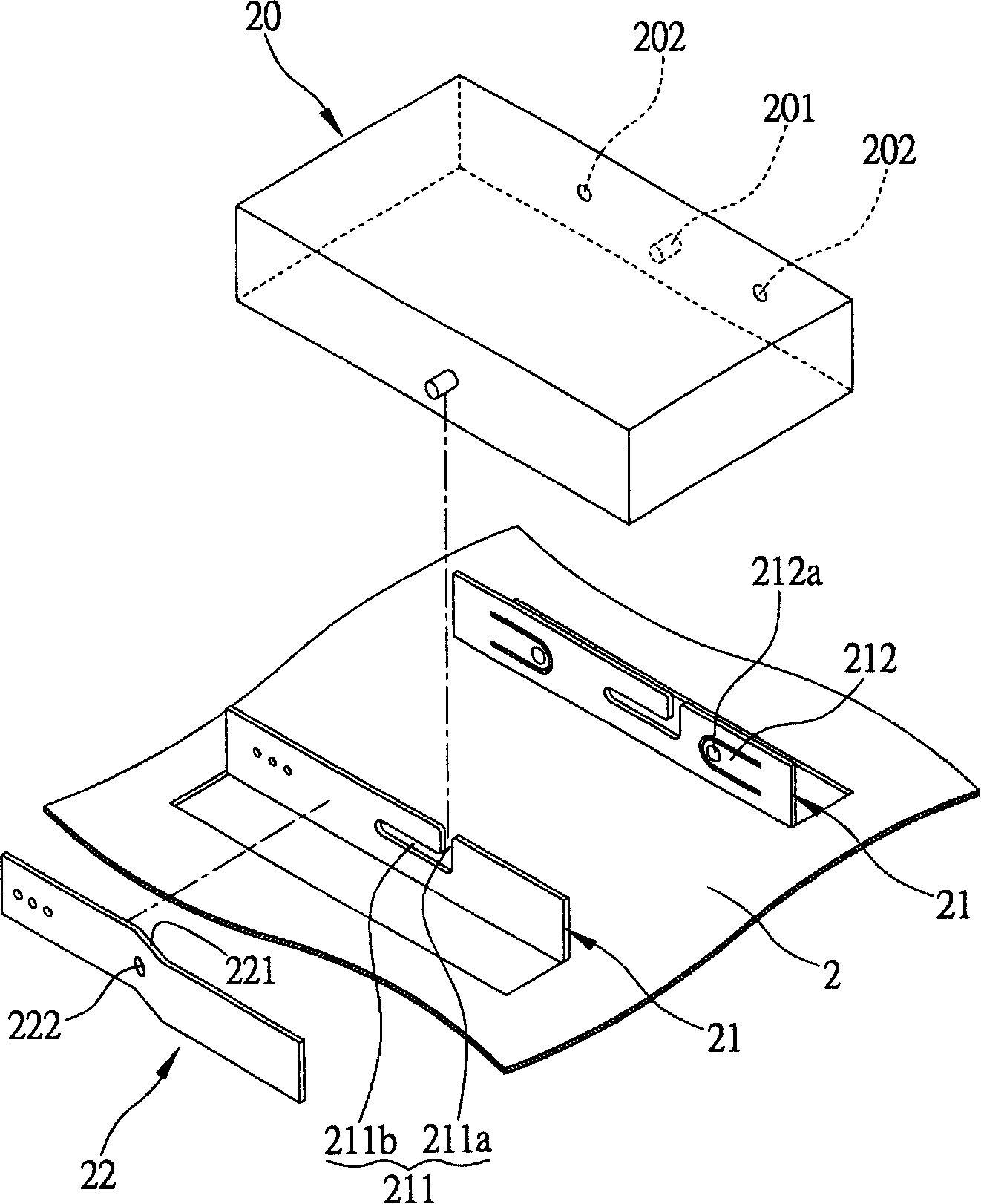
[0049] see Figure 2A, is a perspective view showing the fixing mechanism of the storage device of the present invention, wherein the storage device 20 can be, for example, one of a floppy disk, a hard disk drive, a CD drive, and a burner, and two opposite positioning sides of the storage device 20 are provided with There are fixing posts 201 such as screws or guide posts and a plurality of recesses 202 .

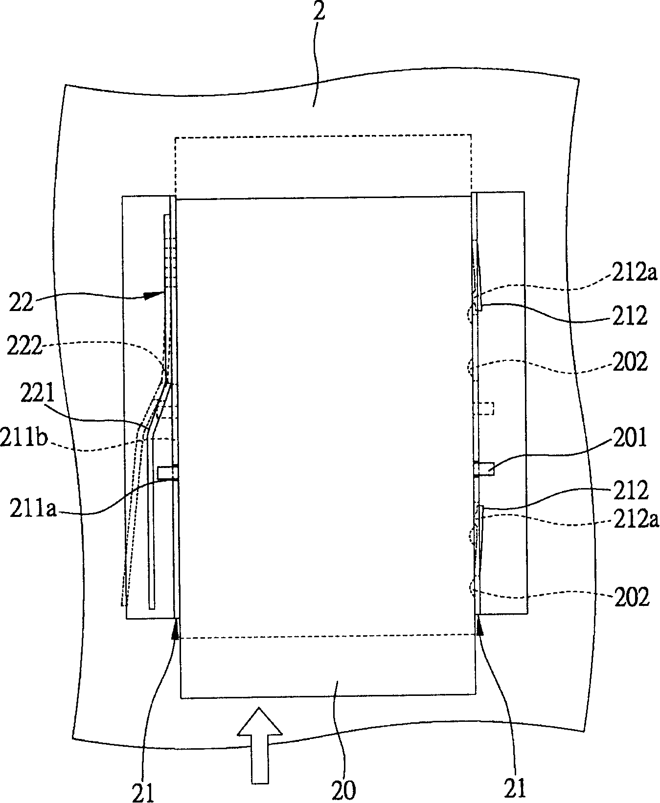
[0050] Two parallel positioning plates 21 are erected on the plane 2 of the casing, and correspond to the positioning side of the storage device 20. The positioning plate 21 is provided with an approximately L-shaped guide groove 211, so that it is located in the storage device. The fixing columns 201 on both sides of the device ...


PUM


Abstract

A storage device fixing mechanism is used for locating and fixing a storage device on a casing plane. The storage device is provided with two opposite locating lateral edges, on which fixing columns are vertically arranged. The fixing mechanism comprises two locating plates and a fixing spring plate. The two locating plates are vertically arranged on the casing plane corresponding to the locating lateral edges, and the locating plates are provided with guide slots for introducing and guiding fixing columns of the storage device to move for localization. The fixing spring plate is arranged on the outer lateral edge of at least one locating plate; one end of the fixing spring plate is fixed to the locating plate, and the other end of the fixing spring plate is a movable end extending along the longitudinal direction of the locating plate; the spring plate is provided with a fixing hole corresponding to guide slots of the locating plates for the fixing columns slid in the guide slots to be embedded in, thereby fixing the storage device on the casing plane.

Description

technical field [0001] The invention relates to a storage device fixing mechanism, in particular to a storage device fixing mechanism which does not need tools for fixing / dismounting. Background technique [0002] In today's era full of information and multimedia, computers have undoubtedly become one of the necessities of human life and work. In recent years, with the continuous improvement of the functions and stability of computers, they have not only replaced the previous large computers Servers are more commonly used in general company lines and families. Computers can be roughly divided into monitors, hosts, and peripherals. The monitors are generally referred to as screens, and peripherals include mice, keyboards, printers, and scanners. The host is responsible for the main data calculation and storage. Work. [0003] The host computer includes a casing, a motherboard, a central processing unit, a memory module, a sound card, a display card, and a data storage devic...

Claims


Application Information

Patent Timeline
IPC IPC(8): G06F1/18H05K7/14
Inventor 宋子雯
Owner INVENTEC CORP
Features
  • Generate Ideas
  • Intellectual Property
  • Life Sciences
  • Materials
  • Tech Scout
  • Unparalleled Data Quality
  • Higher Quality Content
  • 60% Fewer Hallucinations
Learn More