Optical scanning device and image forming apparatus having the same

An optical device and image technology, applied in the fields of optics, image communication, electrical recording technology using charge patterns, etc., can solve problems such as breakage, obstructing the progress of light beams, and displacement of peripheral components, to prevent defects, prevent cleaning spots, and prevent trembling effect

Inactive Publication Date: 2008-05-07
KYOCERA DOCUMENT SOLUTIONS INC
View PDF1 Cites 3 Cited by
  • Summary
  • Abstract
  • Description
  • Claims
  • Application Information

AI Technical Summary

Problems solved by technology

However, dust such as scattered toner adheres to the surface of the translucent member
Therefore, there may be a problem that a correct electrostatic latent image cannot be formed on the surface of the photosensitive drum due to the adhered dust hindering the progress of the light beam.
[0008] However, when the surface of a light-transmitting member such as glass is pressed against an elastic cleaning member such as a rubber squeegee for wiping, if the structure of the elastic cleaning member is not carefully designed, sometimes the light-transmitting member cannot be effectively cleaned. On the surface of parts, there may be problems such as noise during cleaning
[0009] That is, for example, in the case where the entire elastic cleaning member is made of a material with relatively high hardness, it may not be able to adhere uniformly to the surface of the light-transmitting member in the longitudinal direction, that is, in the entire area in the main scanning direction.
Therefore, the effective wiping of the surface of the translucent member cannot be performed by the elastic cleaning member.
As a result, the following problems arise: cleaning spots are generated, which adversely affect beam irradiation, resulting in lower image quality.
[0010] In addition, in the case where the entire elastic cleaning member is made of a material with relatively low hardness, it can be evenly adhered to the surface of the light-transmitting member over the entire area in the main scanning direction, but due to the low hardness, it may not be possible to clean the cleaning member at its contact portion. Strong crimping against the surface of translucent parts
Therefore, there is a problem that the surface of the light-transmitting member of the elastic cleaning member is not wiped sufficiently, and dust such as scattered toner remains, which adversely affects light beam irradiation, resulting in a decrease in image quality.
In addition, there may be chattering while cleaning
Therefore, problems are caused in that large noise is generated, and displacement, deformation, and damage are generated on its peripheral parts due to vibration

Method used


Image

  • Optical scanning device and image forming apparatus having the same
  • Optical scanning device and image forming apparatus having the same
  • Optical scanning device and image forming apparatus having the same

Examples


Embodiment Construction

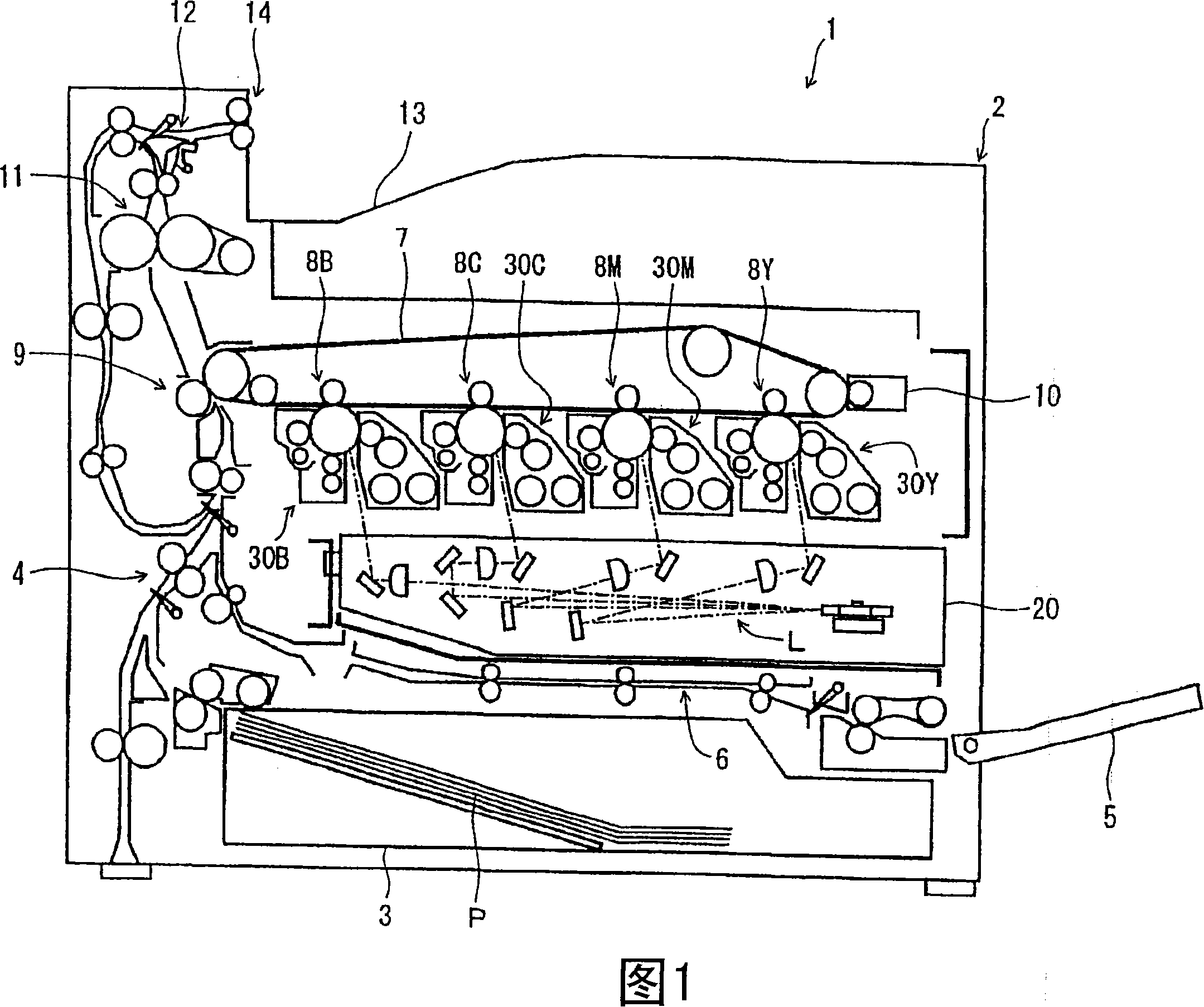
[0029] Hereinafter, embodiments of the present invention will be described with reference to FIGS. 1 to 8 . First, a schematic configuration of an image forming apparatus to which a scanning optical device according to an embodiment of the present invention is mounted will be described with reference to FIG. 1 , and an image output operation will be described. FIG. 1 is a vertical cross-sectional front view of a model of an image forming apparatus. This image forming apparatus is a color printing type apparatus that transfers a toner image onto paper using an intermediate transfer belt.

[0030] As shown in FIG. 1 , a paper cassette 3 is provided under the interior of the main body 2 of the image forming apparatus 1 . The paper cassette 3 stores and accommodates paper P such as cut paper before printing therein. Then, the sheets P are separated and fed one by one toward the upper left of the cassette 3 in FIG. 1 . The paper cassette 3 can be pulled out horizontally from the...


PUM


Abstract

An optical scanning device that permits the surface of an optically transparent member provided at an opening through which a light beam passes to be cleaned with an elastic cleaning member effectively without causing inconveniences such as noise and that offers high image quality has: a housing; an optical arrangement housed inside the housing and irradiating a scanned surface with a light beam; an opening through which the light beam from the optical arrangement travels toward the scanned surface; an optically transparent member provided at the opening; and an elastic cleaning member wiping the surface of the optically transparent member while being kept in pressed contact therewith, the part of the elastic cleaning member making contact with the optically transparent member being formed of a material having a higher hardness than the material of which the part of the elastic cleaning member not making contact with the optically transparent member is formed.

Description

technical field [0001] The present invention relates to a scanning optical device that is mounted on image forming apparatuses such as copiers, printers, and facsimile machines for scanning the surface of an image bearing body by exposure to light beams (eg, laser light). In addition, the present invention also relates to an image forming apparatus of an electrophotographic method, represented by a copier or a printer, in which the scanning optical device is mounted. Background technique [0002] Scanning optical devices used in copiers, printers, etc. generally scan the surface of an image bearing body represented by a photosensitive drum, that is, the surface to be scanned, and perform exposure, thereby forming a predetermined electrostatic latent image on the surface of the photosensitive drum. In the scanning optical device, a light beam such as a laser beam irradiated by a light source is deflected in the main scanning direction by a light deflector, and is emitted towa...

Claims


Application Information

Patent Timeline
Patent Type & Authority Applications(China)
IPC IPC(8): G03G21/00G03G15/04B41J2/47
CPCG03G21/00H04N1/12H04N1/00909H04N1/29H04N1/1135
Inventor 正木彰洋早野聪
Owner KYOCERA DOCUMENT SOLUTIONS INC
Why Eureka
Try Eureka