Load-pressure-controlled feed flow regulator with vibration damping

A technology of load pressure and load control, applied in the direction of control/regulation system, non-electric variable control, pump control, etc., to achieve the effect of precise adjustment and prevention of influence

Inactive Publication Date: 2008-05-07
HYDROMATIK GMBH
View PDF1 Cites 3 Cited by
  • Summary
  • Abstract
  • Description
  • Claims
  • Application Information

AI Technical Summary

Problems solved by technology

This excessive vibration can cause system vibration in a system already sensitive to vibrations per second

Method used


Image

  • Load-pressure-controlled feed flow regulator with vibration damping
  • Load-pressure-controlled feed flow regulator with vibration damping

Examples


Embodiment Construction

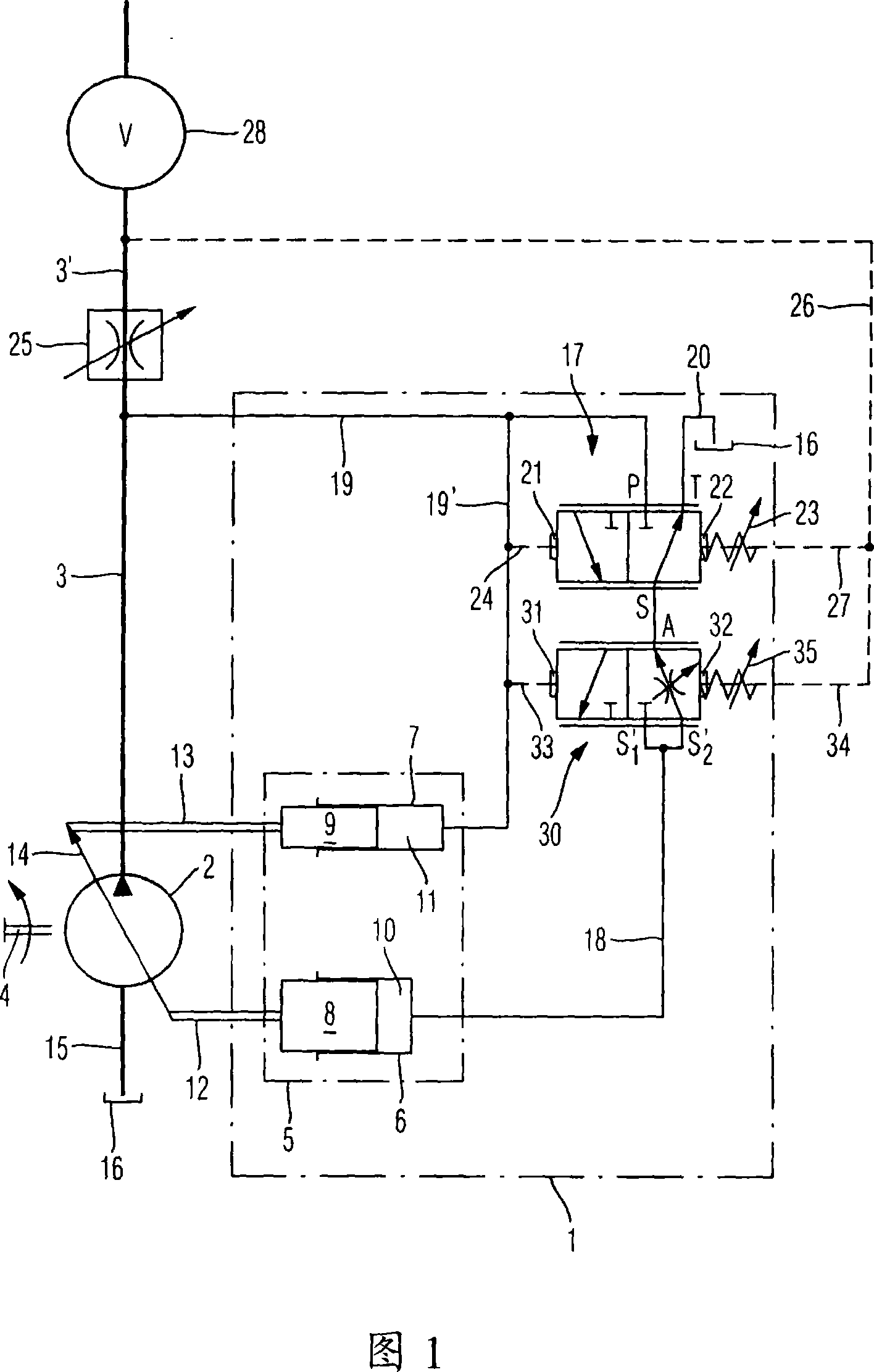
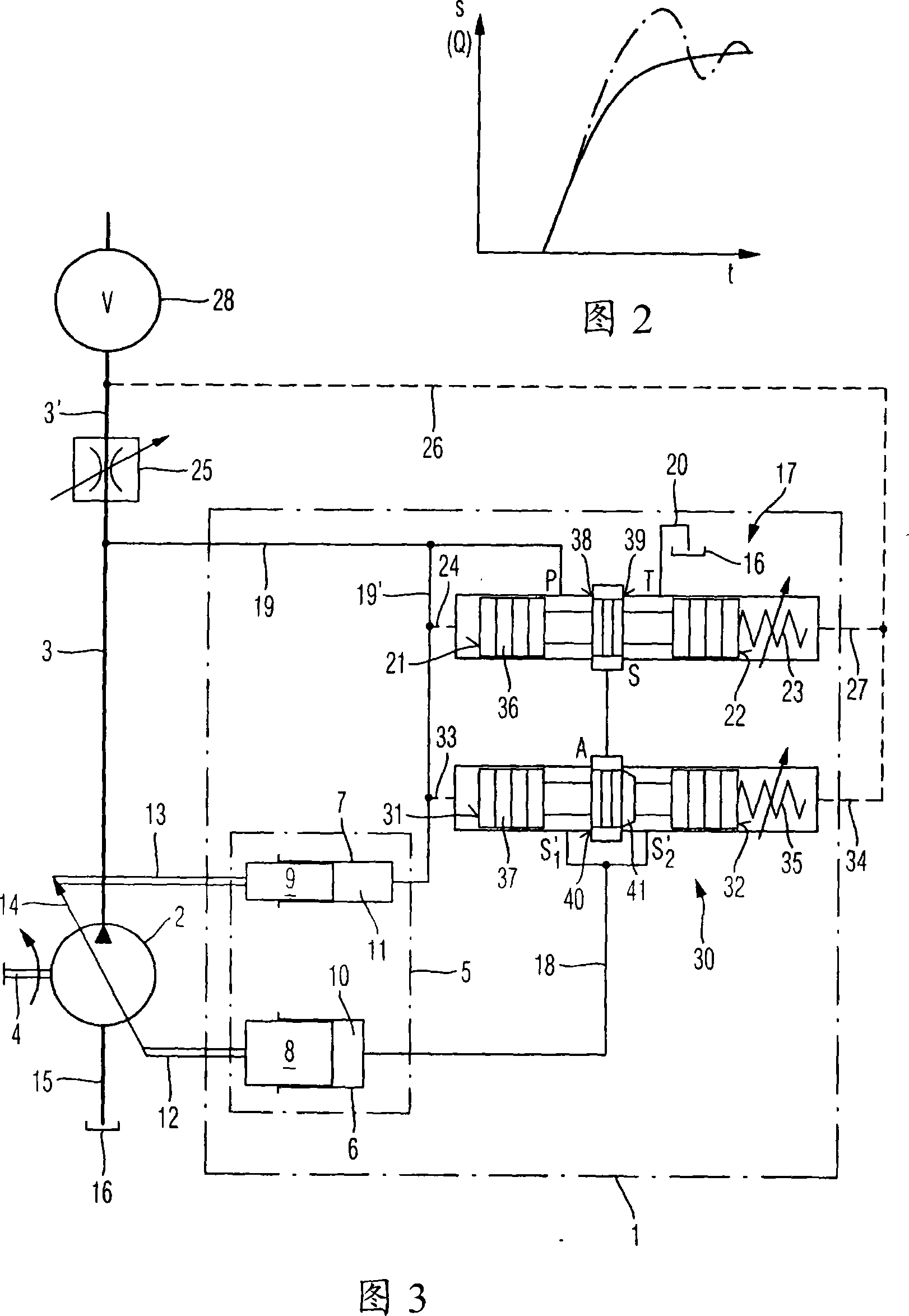
[0019] FIG. 1 shows a hydraulic circuit diagram of a flow rate regulator 1 according to the invention. The delivery volume of the hydraulic pump 2 can be set, and its delivery volume is set to a fixed value by the load pressure-regulated flow rate regulator 1 . The adjustable hydraulic pump 2 may be, for example, a hydrostatic axial piston mechanism. In the exemplary embodiment shown as an example, the adjustable hydraulic pump 2 feeds into the working line 3 . For this purpose, the hydraulic pump 2 is driven via a drive shaft 4 by a drive mechanism, not shown.

[0020] In the exemplary embodiment shown as an example, the adjusting device 5 has a first hydraulic cylinder 6 and a second hydraulic cylinder 7 . In the first hydraulic cylinder 6 a first positioning piston 8 is displaceably arranged. Likewise, in the second hydraulic cylinder 7, a second positioning piston 9 is provided. The first and second positioning piston 8 , 9 seal off the first set pressure chamber 10 or...


PUM


Abstract

The invention relates to a load-pressure-controlled fees flow regulator ( 1 ) for adjusting the feed volume of an adjustable hydraulic pump ( 2 ) which feeds in a working line ( 3 ). The load-pressure-controlled feed flow regulator ( 1 ) has an adjusting device ( 5 ) for adjusting the feed volume of the hydraulic pump ( 2 ). The adjusting device ( 5 ) is acted on with an adjusting pressure in order to adjust the feed volume of the hydraulic pump ( 2 ). The level of the adjusting pressure is generated by an adjusting pressure regulating device ( 17 ). In addition to the adjusting pressure regulating device ( 17 ), the fees flow regulator ( 1 ) has a damping device ( 30 ).

Description

technical field [0001] The invention relates to a flow rate regulator of load pressure control type, which is used for adjusting the delivery volume delivered by an adjustable hydraulic pump to the working pipeline. Background technique [0002] A load pressure-controlled flow rate regulator is known from DE 197 13 934 A1. In order to adjust the set delivery volume delivered by the hydraulic pump to the working pipeline, first and second hydraulic cylinders are provided. A set pressure acting in the second hydraulic cylinder may be set by a control valve when the first hydraulic cylinder is loaded with delivery pressure generated by the hydraulic pump. In order to detect the volumetric flow delivered by the hydraulic pump, an adjustable throttle valve is arranged in the working line. The adjustable throttle valve produces a pressure drop proportional to the volumetric flow delivered in the working line. The pressure differential acts on the control valve against the sprin...

Claims


Application Information

Patent Timeline
Patent Type & Authority Applications(China)
IPC IPC(8): F04B11/00F04B49/08
CPCF15B2211/20553F04B49/08G05D7/0126F04B49/002F04B2205/062F15B2211/6058F04B2205/061F15B2211/41572F15B2211/40515F15B11/165F15B2211/253F15B2211/455Y10T137/7925F04B11/00
Inventor 莱因霍尔德·施内德让
Owner HYDROMATIK GMBH
Why Eureka
Try Eureka