
Rotation drive force transmission mechanism, constant velocity universal joint and resin joint boot constructing the mechanism, and method of tightening clamp band for constant velocity universal join

A constant velocity universal joint and driving force technology, which is applied to mechanical equipment, elastic couplings, couplings, etc., can solve the problems of installation position limitation, joint cover manufacturing cost increase, etc., and achieve the effect of favorable sealing ability

Inactive Publication Date: 2008-05-07
HONDA MOTOR CO LTD
View PDF4 Cites 8 Cited by
  • Summary
  • Abstract
  • Description
  • Claims
  • Application Information

AI Technical Summary

Problems solved by technology

However, the protective cover requires installation space to avoid interference between the protective cover and the floor of the vehicle body, and its installation position is limited
In addition, the use of protective covers leads to increased manufacturing costs for the splice housings

Method used


Image

  • Rotation drive force transmission mechanism, constant velocity universal joint and resin joint boot constructing the mechanism, and method of tightening clamp band for constant velocity universal join
  • Rotation drive force transmission mechanism, constant velocity universal joint and resin joint boot constructing the mechanism, and method of tightening clamp band for constant velocity universal join
  • Rotation drive force transmission mechanism, constant velocity universal joint and resin joint boot constructing the mechanism, and method of tightening clamp band for constant velocity universal join

Examples


Embodiment Construction

[0097] A rotational drive force transmission mechanism, a constant velocity universal joint for the mechanism, a resin-made joint cover, and a method of crimping a belt according to an embodiment of the present invention will be described below with reference to the accompanying drawings. This rotational drive force transmission mechanism is generally incorporated in motor vehicles such as automobiles.

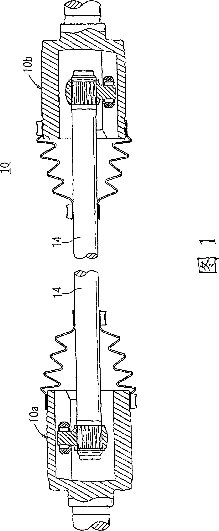
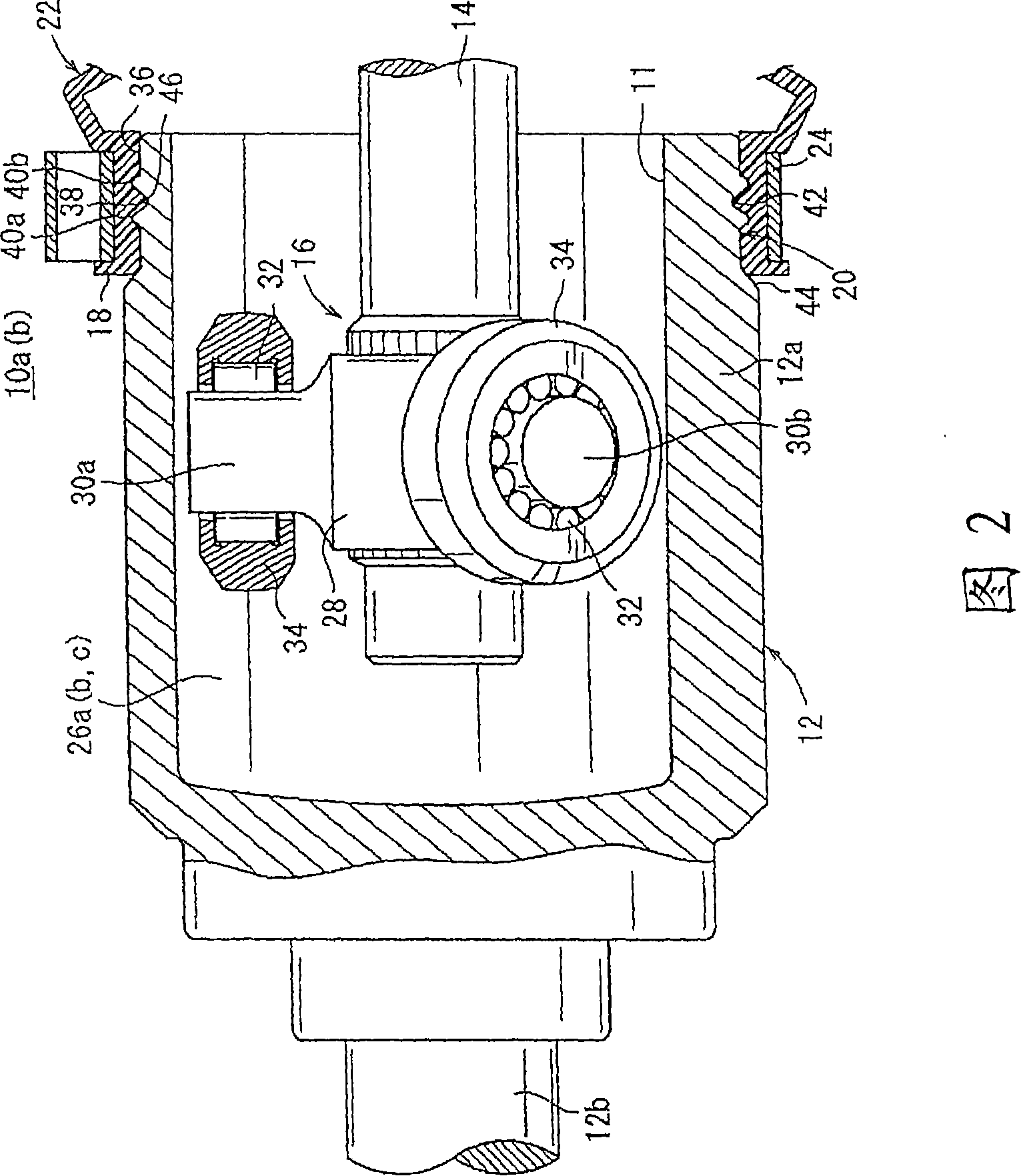
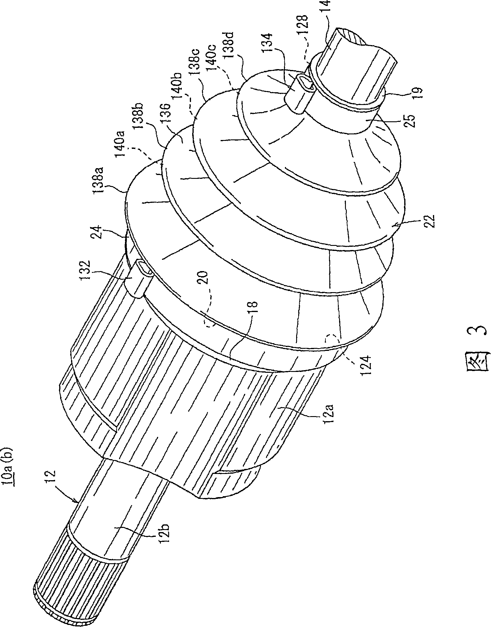
[0098] FIG. 1 is a longitudinal sectional view taken along the axial direction of a rotational driving force transmission mechanism 10 according to an embodiment of the present invention. As shown in FIG. 1, the rotational driving force transmission mechanism 10 includes a shaft 14, a first tripod type constant velocity universal joint 10a coupled to one end of the shaft 14 for axial sliding movement on the shaft, and The other end of 14 is used for the second tripod type constant velocity universal joint 10b for axial sliding movement on the shaft. The first tripod type cons...


PUM


Abstract

The present invention relates to a rotation drive force transmission mechanism (10), method for forming constant speed universal joint and resin joint covering as well as holding belt tensioning for the constant speed universal joint. Where tripod constant velocity universal joints (10a, 10b) are connected in phases opposite to each other to the ends of a shaft (14), and a boot (22) covers from an outer member (12) of each tripod constant velocity universal joint (10a, 10b) to the shaft (14). When a large diameter tube section (18) of the boot (22) is tightened around the outer member (12) by a first clamp band (24), a band tightening rate is controlled to be in a predetermined region. Further, the shape of a boot installation section (20) of the outer member (12) is formed so as to satisfy a predetermined relational expression.

Description

technical field [0001] The present invention relates to a rotary drive force transmission mechanism, a constant velocity (universal) joint for the mechanism and a joint cover made of resin, and a crimp or tension fastening (clamping) belt to The method by which the fastening strap is positioned and secured to the outer member of the constant velocity universal joint. Background technique [0002] A motor vehicle such as an automobile has a rotational driving force transmission mechanism for transmitting rotational driving force generated by various prime movers such as an internal combustion engine, a motor, etc. to tires. The rotary drive transmission mechanism typically employs a constant velocity universal joint to transmit the rotary drive from one shaft to the other. [0003] In an effort to simplify the transmission structure of the driven shaft power transmission system and reduce its size and weight, the applicant of the present application has proposed a driven for...

Claims


Application Information

Patent Timeline
Patent Type & Authority Applications(China)
IPC IPC(8): F16D3/84
Inventor 大久保茂
Owner HONDA MOTOR CO LTD
Learn More