Composite magnetic powder and compaction magnet core using the same

A composite magnetic powder and soft magnetic technology, which is applied in the field of dust cores, can solve the problems of iron loss reduction and achieve the effect of improving contact resistance and high resistivity

Active Publication Date: 2015-07-22
ALPS ALPINE CO LTD
View PDF4 Cites 0 Cited by
  • Summary
  • Abstract
  • Description
  • Claims
  • Application Information

AI Technical Summary

Problems solved by technology

[0003] In addition, in order to achieve reduction in iron loss, etc., it is preferable that the electrical resistivity of the dust core is high, but there is no patent document that rationalizes the structure from the inside to the surface of the composite magnetic powder in order to obtain high electrical resistivity.

Method used


Image

  • Composite magnetic powder and compaction magnet core using the same
  • Composite magnetic powder and compaction magnet core using the same
  • Composite magnetic powder and compaction magnet core using the same

Examples


Embodiment Construction

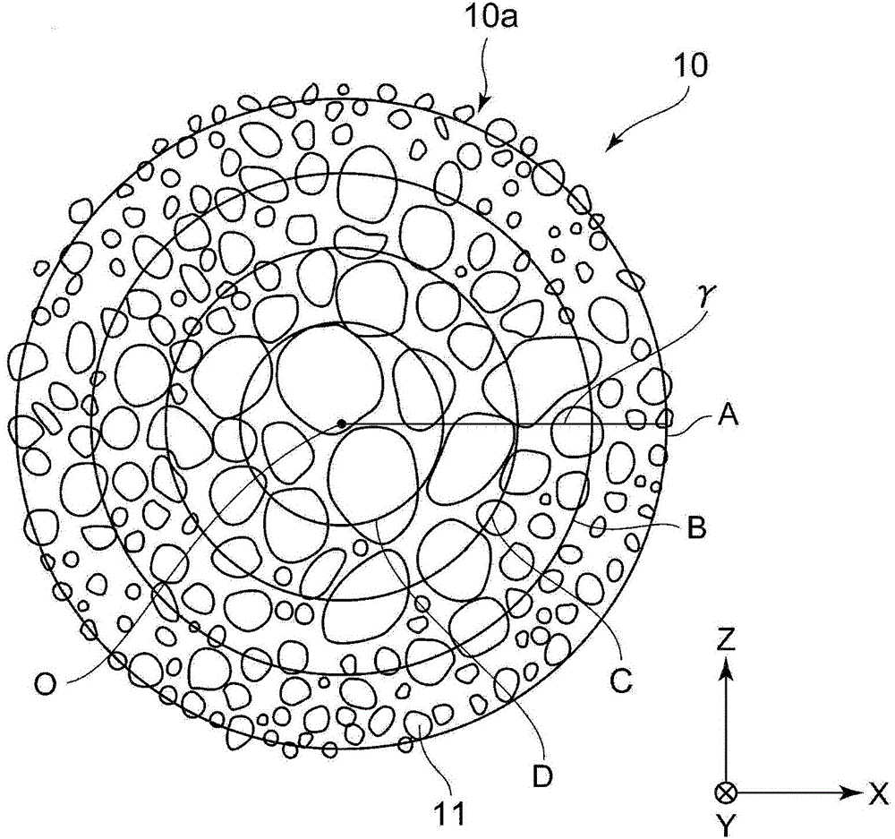
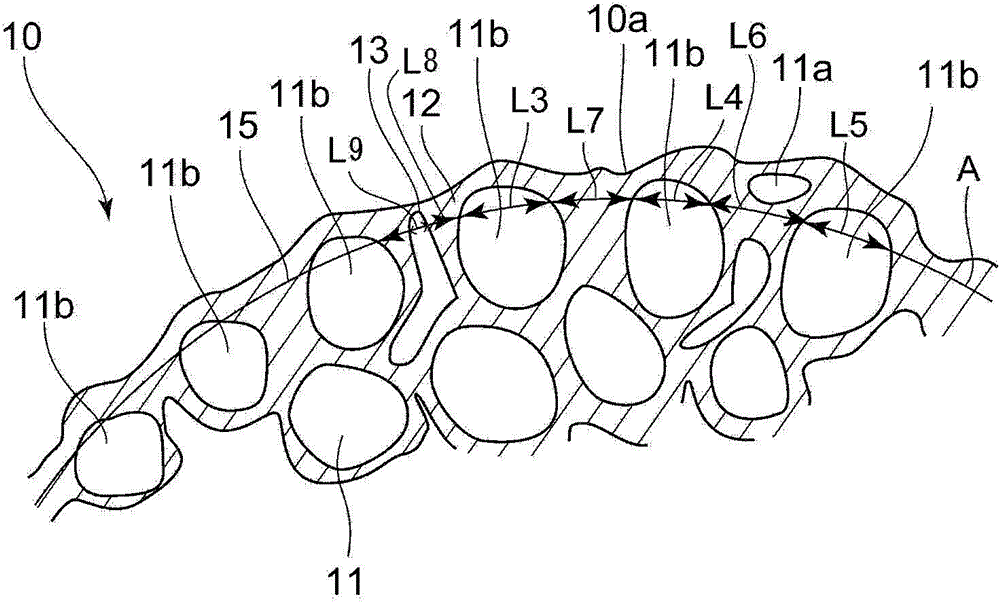
[0069] figure 1 It is a schematic diagram showing the cross section of the composite magnetic powder of this embodiment, figure 2 will be figure 1 A schematic diagram of a composite magnetic powder according to the present embodiment shown enlarged.

[0070] figure 1 The composite magnetic powder (granulated powder) 10 of the present embodiment shown is obtained by using a binder resin ( figure 1 Not shown in ) by bonding soft magnetic particles 11 together. Among them, in figure 1 In , only one soft magnetic particle 11 is given a symbol 11 .

[0071] figure 1 A cross section passing through the approximate center O of the composite magnetic powder 10 is shown. Here, "center" may be defined as the geometric center point. If the composite magnetic powder 10 is approximately spherical or approximately ellipsoidal, the point where the midpoints in the X, Y, and Z directions intersect is the center. In addition, "center" may be defined as "center of gravity".

[0072] ...


PUM

PropertyMeasurementUnit
particle sizeaaaaaaaaaa
particle diameteraaaaaaaaaa
thicknessaaaaaaaaaa

Abstract

PURPOSE: A composite magnetic powder and a dust core using the same are provided to form constant resistance of a surface of each composite magnetic powder by cohering binder resin on a surface of composite magnetic powder. CONSTITUTION: Magnetic material powder(10) is formed by combining a soft magnetic particle(11). The magnetic material powder is coated on a binder resin. The most surface of the magnetic material does not include a soft magnetic particle. A surface approximation line A is located inside composite magnetic powder. The surface approximation line A puts a line of a soft magnetic particle.

Description

technical field [0001] The present invention relates to a composite magnetic powder composed of a plurality of soft magnetic particles bonded to an insulating binder resin, and a dust core using the composite magnetic powder. Background technique [0002] Dust cores used in step-up circuits of hybrid vehicles, reactors for power generation and transformation equipment, transformers, choke coils, etc. The powder is obtained by pressing powder. There are descriptions of composite magnetic powder (granulated powder) in the following patent documents. [0003] In addition, in order to achieve a reduction in iron loss, etc., it is preferable that the electrical resistivity of the dust core is high, but there are no patent documents that rationalize the structure from the inside to the surface of the composite magnetic powder in order to obtain high electrical resistivity. [0004] 【Prior technical literature】 [0005] 【Patent Literature】 [0006] [Patent Document 1] Japanese ...

Claims


Application Information

Patent Timeline
Patent Type & Authority Patents(China)
IPC IPC(8): H01F1/20H01F1/26H01F3/08
CPCB22F3/10C04B35/626H01F1/086H01F1/14758H01F1/15366
Inventor 小柴寿人土屋景子冈本淳
Owner ALPS ALPINE CO LTD
Why Eureka
Try Eureka