
Resistance Limited Phase Change Memory Material

Inactive Publication Date: 2008-07-10
IBM CORP +2
View PDF4 Cites 116 Cited by
  • Summary
  • Abstract
  • Description
  • Claims
  • Application Information

AI Technical Summary

Benefits of technology

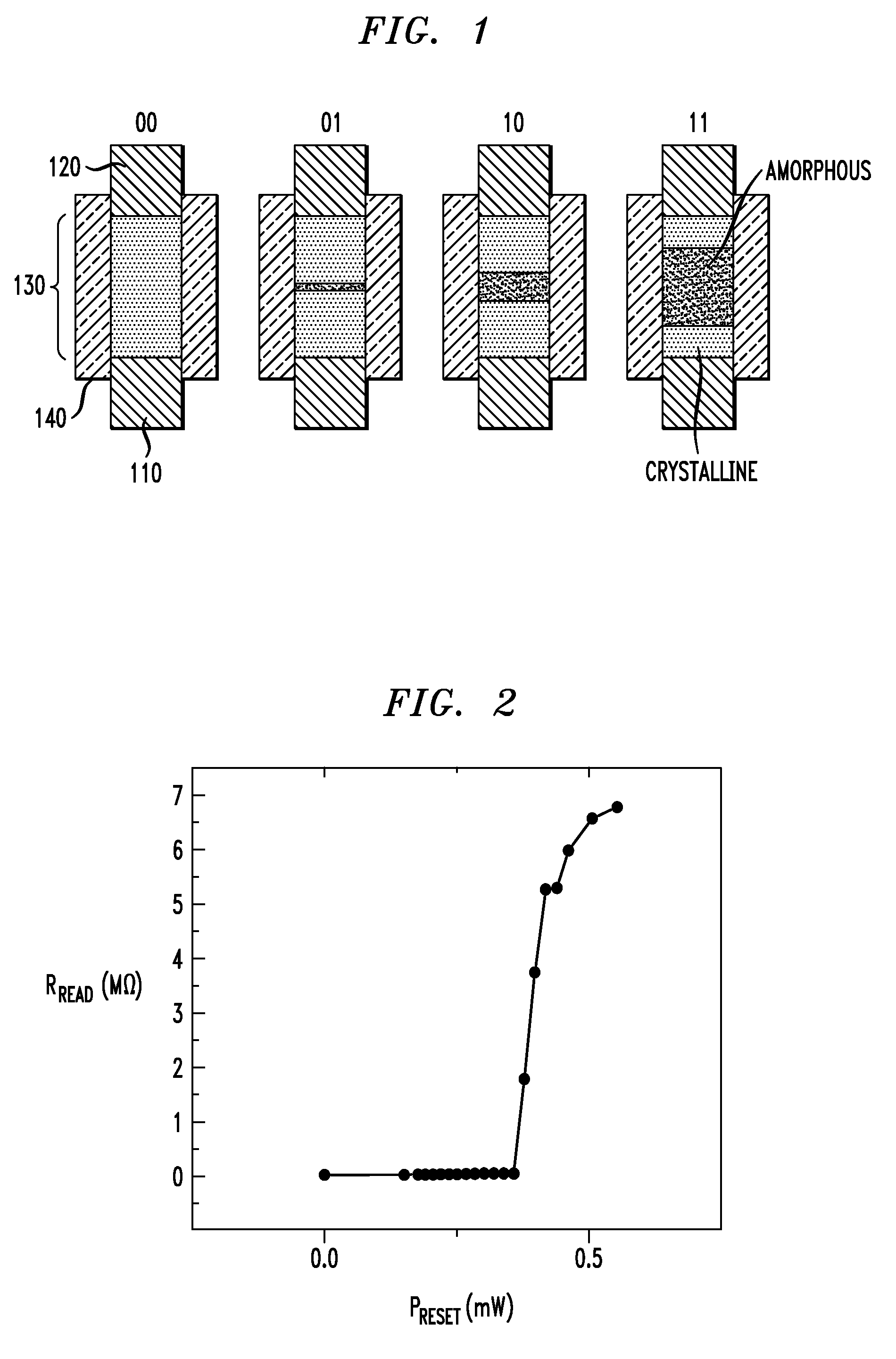
[0006]Embodiments of the present invention address the above-identified needs by providing a multibit PCM-based memory cell design that allows the incorporated PCM to be configured into a higher resistivity phase without causing the memory cell to have an extremely high overall resistance value and a relatively slow reading speed.
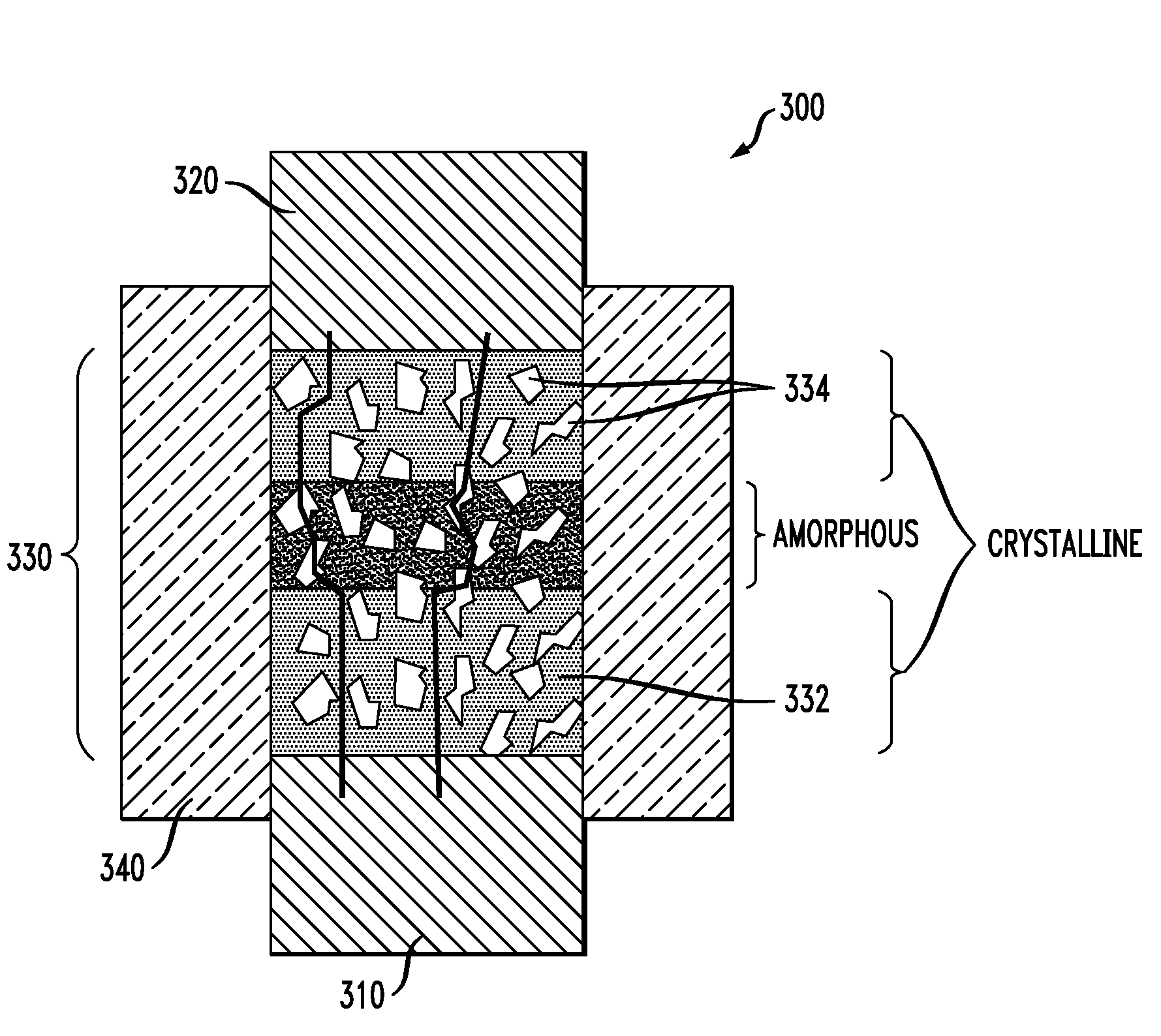
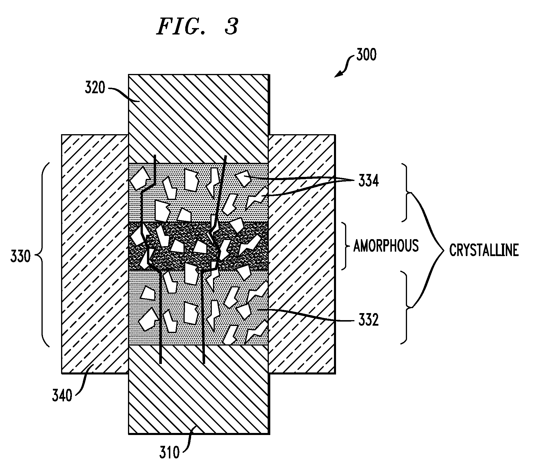
[0008]In accordance with an illustrative embodiment of the invention, a memory cell comprises a lower electrode and an upper electrode between which is disposed a composite material. The composite material comprises a PCM interspersed with a multiplicity of resistor clusters. At least a portion of the PCM is operative to switch between a lower resistivity crystalline phase and a higher resistivity amorphous phase in response to the passing of a pulse of current through the composite material. The resistor clusters, in turn, comprise a resistor material that has a lower resistivity than the PCM when the PCM is in its higher resistivity amorphous phase. Advantageously, when reading the memory cell having at least a portion of the PCM is in its higher resistivity amorphous phase, some of the read current passes through the resistor clusters. The overall resistance of the memory cell is thereby reduced by using the composite material rather than using a PCM alone. Reading speed may thereby be enhanced.

Problems solved by technology

Unfortunately, as a result of these high resistance values, typically only a small current is detectible when reading the memory cell in one of these higher resistance states.
As a result, the reading speed for the memory cell is adversely affected.

Method used


Image

  • Resistance Limited Phase Change Memory Material
  • Resistance Limited Phase Change Memory Material
  • Resistance Limited Phase Change Memory Material

Examples


Embodiment Construction

[0019]The present invention will be described with reference to illustrative embodiments. For this reason, numerous modifications can be made to these embodiments and the results will still come within the scope of the invention. No limitations with respect to the specific embodiments described herein are intended or should be inferred.

[0020]Particularly with respect to processing steps, it is emphasized that the descriptions provided herein are not intended to encompass all of the processing steps which may be required to successfully form a functional integrated circuit device. Rather, certain processing steps which are conventionally used in forming integrated circuit devices, such as, for example, wet cleaning and annealing steps, are purposefully not described herein for economy of description. However one skilled in the art will readily recognize those processing steps omitted from these generalized descriptions. Moreover, details of the processing steps used to fabricate such...


PUM


Abstract

A memory cell comprises a first electrode, a second electrode and a composite material. The composite material electrically couples the first electrode to the second electrode. Moreover, the composite material comprises a phase change material and a resistor material. At least a portion of the phase change material is operative to switch between a substantially crystalline phase and a substantially amorphous phase in response to an application of a switching signal to at least one of the first and second electrodes. In addition, the resistor material has a resistivity lower than that of the phase change material when the phase change material is in the substantially amorphous phase.

Description

FIELD OF THE INVENTION [0001]The present invention is directed generally to memory circuitry and, more particularly, to phase change memories.BACKGROUND OF THE INVENTION [0002]The possibility of using phase change materials (PCMs) in nonvolatile memory cells has recently gained momentum as more is learned about these materials and their integration into integrated circuits. When incorporated in a memory cell, for example, these materials may be toggled between higher and lower electrical resistivity phases by applying a pulse of electrical current (“switching current pulse”) to the memory cell which acts to heat the PCM. Applying a switching current pulse that results in the PCM heating above its crystallization temperature causes the PCM to achieve a relatively low resistivity crystalline phase. Applying a larger magnitude switching current pulse (often called a “RESET” current pulse), on the other hand, causes the PCM to melt and to enter a relatively high resistivity amorphous ph...

Claims


Application Information

Patent Timeline
IPC IPC(8): G11C11/00H01L21/06H01L21/00
CPCG11C11/5678G11C13/0004H01L45/1625H01L45/1233H01L45/144H01L45/06H10N70/231H10N70/826H10N70/8828H10N70/026
Inventor CHEN, CHIEH-FANGCHEN, SHIH-HUNGCHEN, YI-CHOUHAPP, THOMASHO, CHIA HUAHSUEH, MING-HSIANGLAM, CHUNG HONLUNG, HSIANG-LANPHILIPP, JAN BORISRAOUX, SIMONE
Owner IBM CORP
Learn More