

Discharge lamp lighting device and projector
- Summary
- Abstract
- Description
- Claims
- Application Information
AI Technical Summary
Benefits of technology
Problems solved by technology
Method used
Image

Examples
embodiment 1
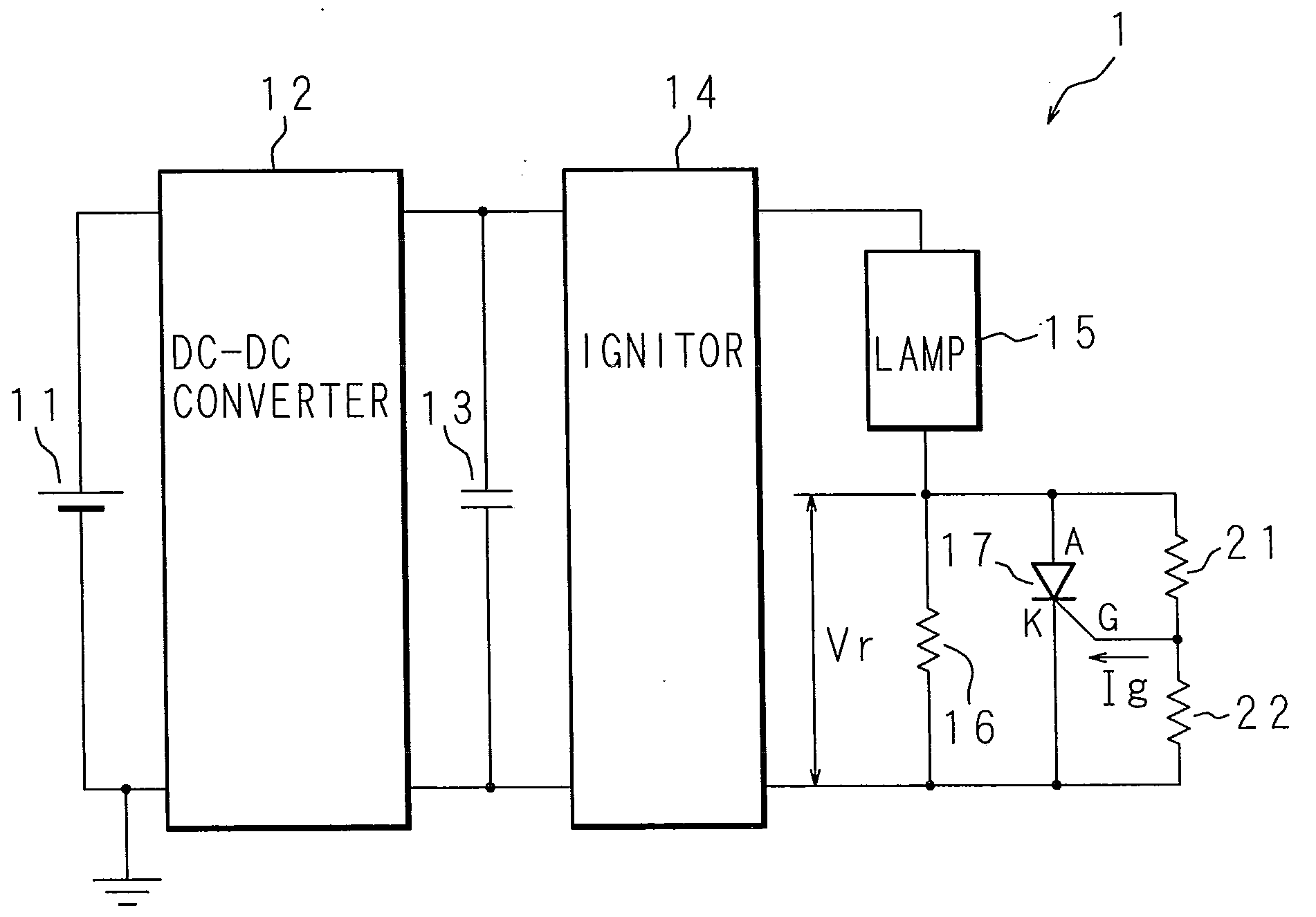
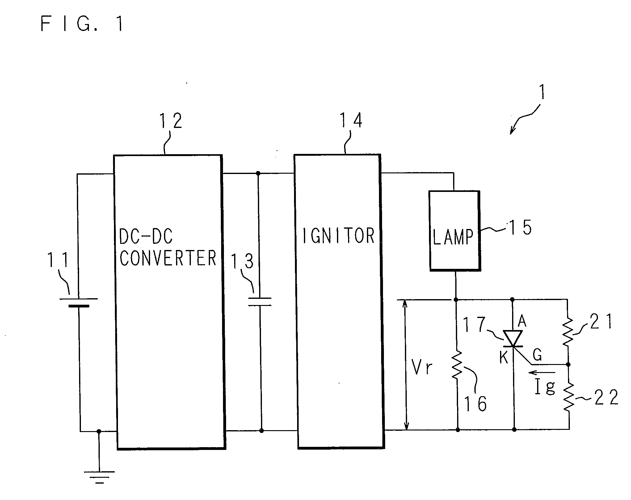
[0029]The following description will explain Embodiments of the present invention, based on the drawings. FIG. 1 is a circuit diagram showing circuitry of a discharge lamp lighting device 1. In FIG. 1, 1 denotes the discharge lamp lighting device (hereinafter, lighting device 1), and is constructed including a direct-current power supply 11, a DC-DC converter 12, a capacitor 13, an ignitor 14, a discharge lamp (hereinafter, lamp) 15, a resistor 16, a silicon controlled rectifier (thyristor) 17, an auxiliary resistor 21, and a protective resistor 22. The DC-DC converter 12 is connected to the direct-current power supply 11. The capacitor 13 is connected in parallel with the latter part thereof, and the ignitor 14 is connected to the latter part thereof. The DC-DC converter 12 raises or lowers voltage from the direct-current power supply 11, and controls lighting so that power to be supplied to the lamp 15 becomes a rated value of the lamp 15 by turning on / off a not-shown switching el...
embodiment 2
[0044]Embodiment 2 relates to an embodiment in which reduces more power consumption by additionally connecting a switching element in parallel and turning on the switching element after elapse of a predetermined time. FIG. 3 is a circuit diagram showing the circuitry of a lighting device 1 according to Embodiment 2. In addition to the constitution of Embodiment 1, the lighting device 1 is constructed including a switching element 18, a switching controller 181, a timer 182, a current detecting circuit 183, and a current detecting resistor 184. As the switching element 18, for example, a FET (hereinafter, FET 18) is used. The FET 18 is connected in parallel with the resistor 16, the thyristor 17, and the auxiliary resistor 21 and the protective resistor 22.
[0045]The FET 18 has a drain connected to the lamp 15, a source connected between the ignitor 14 and resistor 16, and a gate connected to the switching controller 181. The switching controller 181 alternatively outputs to the FET 1...
embodiment 3
[0050]The above mentioned lighting device 1 is applied to a projector. FIG. 4 is a block diagram showing a hardware configuration of the projector. The projector 30 is constituted including the lighting device 1 of Embodiment 1 or 2, the lamp 15, a reflecting mirror 321, a color wheel 32, an image forming device (hereinafter DMD (Digital Micromirror Device (registered trademark)) 36, an image forming device control circuit 37, a projector lens 38, a fan 33, a main control section 39, and a video signal processing section 391.
[0051]The main control section 39 controls the above mentioned respective parts of hardware according to a program stored in a not-shown memory. A video signal is inputted to the video signal processing section 391. The video signal processing section 391 performs processing on the video signal, such as synchronizing separation and scaling, etc. and outputs a processed video signal to the image forming device control circuit 37. In the projector 30, white light ...
PUM
 Abstract
Description
Claims
Application Information