Friction stir welding tool comprising a retractable guide member and a welding process

Active Publication Date: 2016-03-31
STELIA AEROSPACE
View PDF6 Cites 2 Cited by
  • Summary
  • Abstract
  • Description
  • Claims
  • Application Information

AI Technical Summary

Benefits of technology

[0030]Thanks to the method of the invention, the guide member can be moved from a guiding position to a retracted position to avoid a barrier during welding. Thus, the welding tool can fully weld an interface line of two panels with the same welding tool during the same welding step while ensuring adequate pressing of the elements. Preferably, the said elements may be in the form of two panels, a stiffener or a single panel, etc.
[0031]Preferably, the displacement

Problems solved by technology

Such a solution has the disadvantage of forming a non-uniform welding bead.
For these reasons, such a solution cannot be adopted.
Such a solution has the disadvantage of forming a non-uniform connection of the interface line 20.
Furthermore, in addition to

Method used


Image

  • Friction stir welding tool comprising a retractable guide member and a welding process
  • Friction stir welding tool comprising a retractable guide member and a welding process
  • Friction stir welding tool comprising a retractable guide member and a welding process

Examples


Example

[0039]It must be noted that the figures provide a detailed description of the invention in order to implement the invention; the said figures may be used to better define the invention if necessary.

DETAILED DESCRIPTION

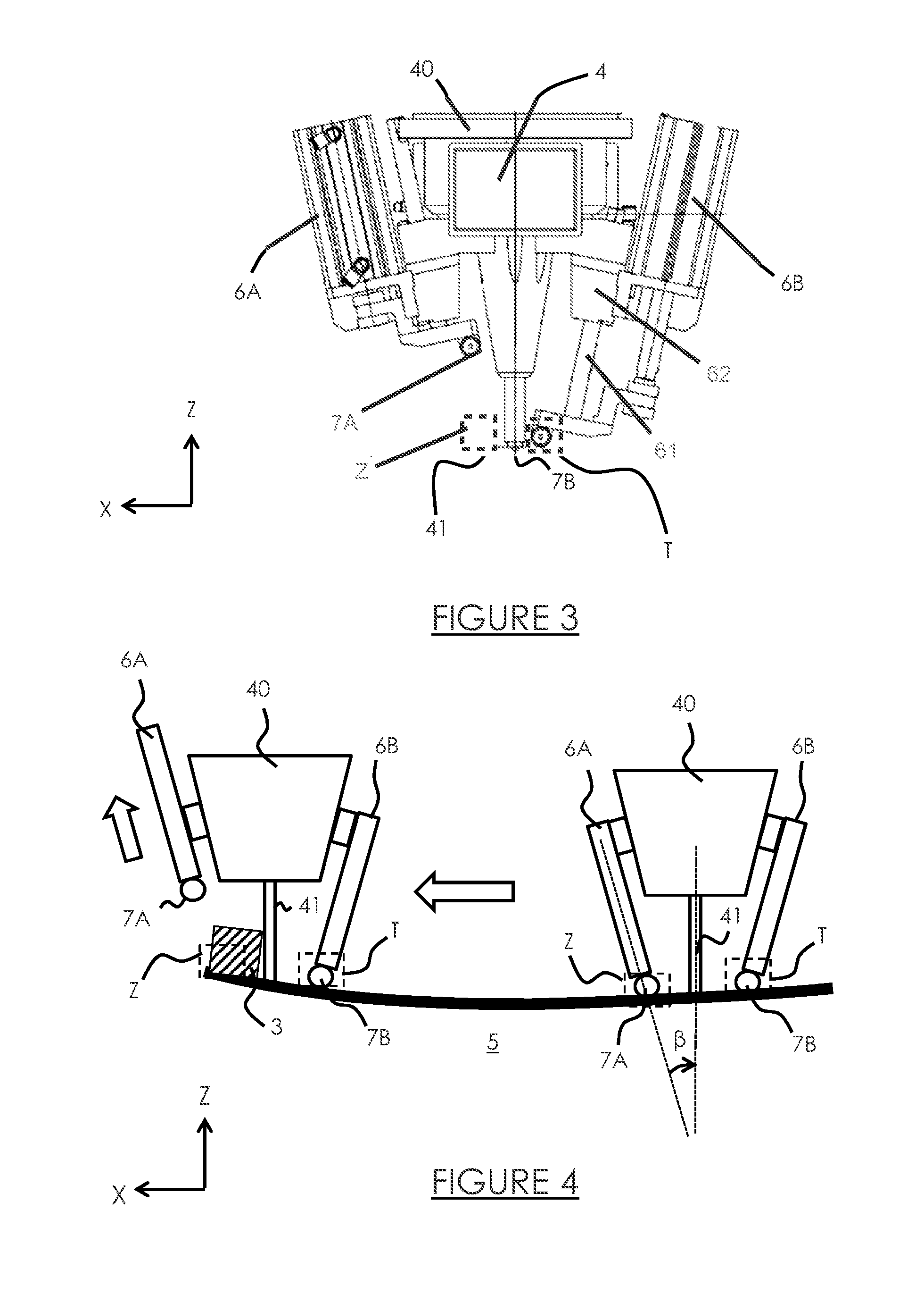
[0040]Referring to FIG. 3, there is a welding tool 4 according to the invention which comprises a base 40 and a rotating friction stir slug 41 mounted in the said base 40. The friction stir slug 41 is positionable to a welding position to perform a weld along an interface line of two surfaces to be joined, such as two panels. For example, the friction stir slug can move to the welding position to perform a weld and can retract away from the welding position. Such a structure is known to those skilled in the art and will not be discussed in more detail.

[0041]The welding tool 4 is adapted to move longitudinally in the downstream direction along the X axis oriented from upstream to downstream.

[0042]According to the invention, the welding tool 4 comprises two guide members...


PUM

PropertyMeasurementUnit
Angleaaaaaaaaaa
Angleaaaaaaaaaa
Forceaaaaaaaaaa

Abstract

A friction stir welding tool with a base, a rotating friction stir slug mounted in the said base and at least one guide member connected to the said base, the welding tool being adapted to move from upstream to downstream; a welding tool having at least one displacement member of the guide member relative to the said base between at least one guiding position in which the guide member extends in a scout area located downstream and facing the friction stir slug and at least one retracted position in which the guide member is offset from the said scout area.

Description

GENERAL TECHNICAL FIELD AND PRIOR ART[0001]This invention relates to the field of welding of fuselage panels of an aircraft, and more particularly, the friction stir welding for joining panels of the nose of the fuselage of an aircraft. The soudage par friction malaxage (French) is known to those skilled in the art under its English name “Friction Stir Welding” or “FSW”.[0002]The nose of an aircraft fuselage is manufactured in a known manner by the edge to edge joining of multiple structural panels. To do this, the edges of the panels to be joined are first machined separately and then welded together.[0003]During the implementation of a method involving friction stir welding of two panels to be joined, the latter are first held firmly against each other on an anvil. Then, a welding tool comprising a friction stir slug is pressed into the material at the interface of the two panels. The pressing force applied continuously by the slug and the rotation of said slug generate friction a...

Claims


Application Information

Patent Timeline
IPC IPC(8): B23K20/12
CPCB23K20/1205B23K20/1245B23K20/129B23K20/126
Inventor LAMBERT, OLIVIERLUC, GUILLAUME
Owner STELIA AEROSPACE
Why Eureka
Try Eureka