Upper-strand well for a trough pan and trough pan having such an upper-strand well

Active Publication Date: 2012-04-05
CATERPILLAR INC
View PDF13 Cites 2 Cited by
  • Summary
  • Abstract
  • Description
  • Claims
  • Application Information

AI Technical Summary

Benefits of technology

[0008]The boundary line at the end edges is preferably provided with a central curved zone and, on the outside, with multiply angled zones, in order to ensure good angular movability of adjacent trough pans or upper strand troughs with respect to one another.
[0009]In a trough pan according to the invention, in addition to the measures according to the invention taken on the upper strand trough, further structural variations will be carried out in order to improve overall the service life of the trough pan. Thus, according to an advantageous refinement, the intermediate bottom may be provided, near its terminal edges, partially with clearances or holes, as has already been tried out per se, although substantially less fine coal has to be discharged into the lower strand via the clearances or holes that are also provided than in the prior art, since the bulk of the fine coal material accumulating in the gap creeps upward out of the joint gap as a result of the self-cleaning effect. The clearances are preferably composed of oval long holes arranged transversally to the running direction of the scrapers or approximately parallel to the end edge. Also preferably, the intermediate bottom may be provid

Problems solved by technology

When an exchangeable upper strand trough supported on an intermediate bottom has been in operational use for a lengthy period, sometimes considerable accumulations of fine coal appear in the gap at the joint between the trough plates of adjacent upper strand troughs, and this fine coal may be additionally compacted as a result of the movement of the scrapers and in adverse cases may even infiltrate between the trough bottom and intermediate bottom.

Method used


Image

  • Upper-strand well for a trough pan and trough pan having such an upper-strand well
  • Upper-strand well for a trough pan and trough pan having such an upper-strand well
  • Upper-strand well for a trough pan and trough pan having such an upper-strand well

Examples


Example

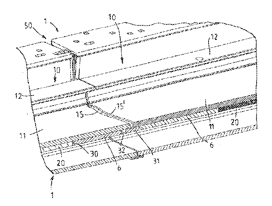
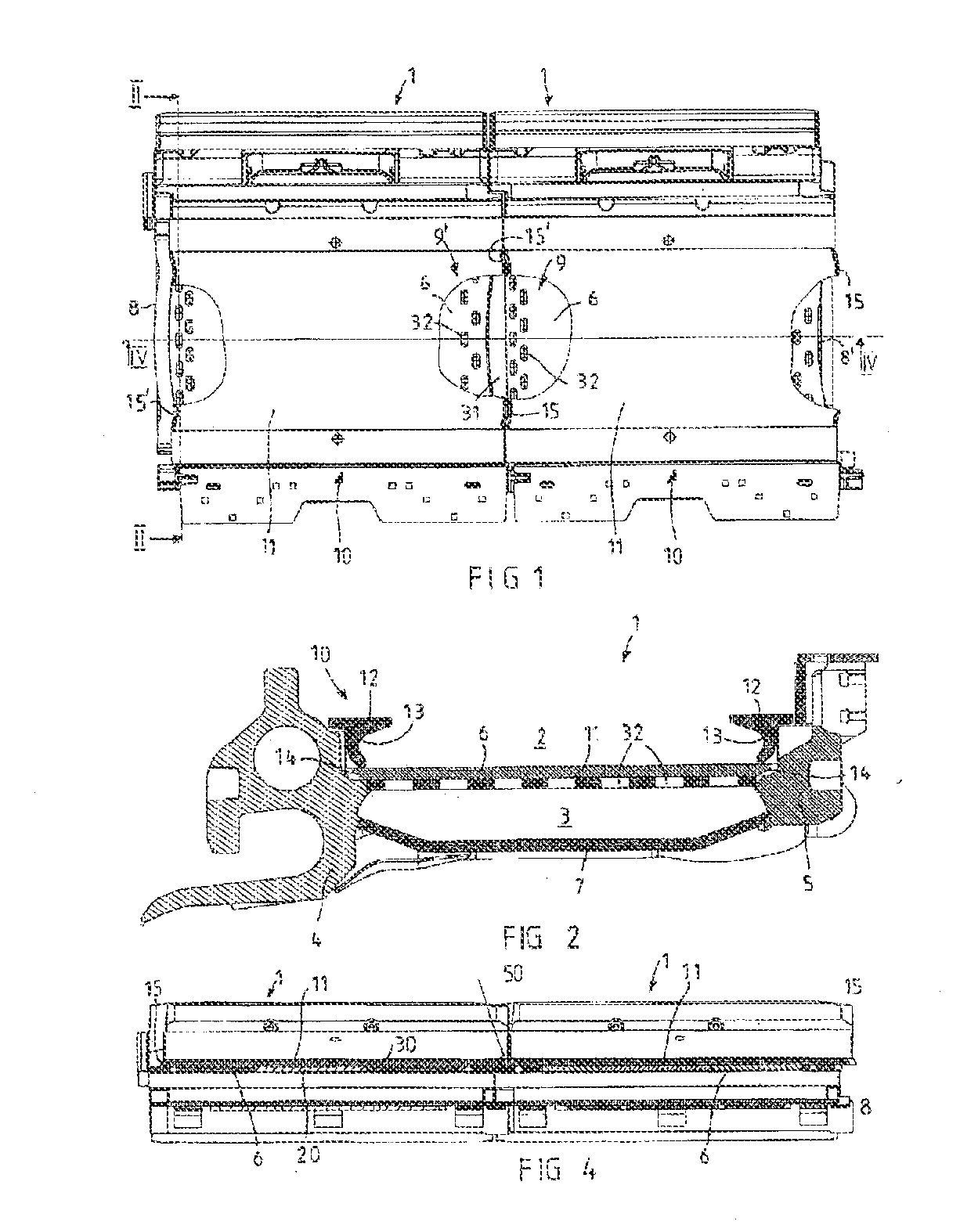
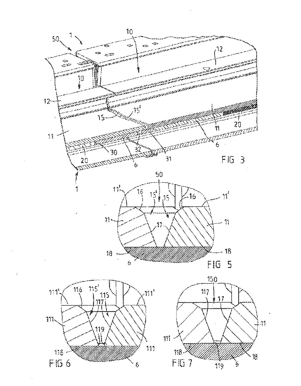
[0019]Referring now to the drawings wherein the showings are for the purpose of illustrating preferred and alternative embodiments of the invention only and not for the purpose of limiting same, FIGS. 1 to 4 show a trough pan according to the invention is designated in each case by reference symbol 1. A scraper chain conveyor, such as is installed, for example, in the underground longwall face of a coal mining plant, is mostly composed of a multiplicity of, for example more than 200, identically constructed trough pans 1, at the end of which drive troughs are positioned, in order to move a rotating scraper belt with connected scrapers (not illustrated) in an upper strand 2 of the individual trough pans 1 in one direction and to return it by rotation in the lower strand 3. As may be gathered clearly particularly from FIG. 2, in the exemplary embodiment shown the trough pan 1 is composed of a first side cheek 4, which has here at the same time integrally a planar guide and which is co...


PUM


Abstract

A trough pan with an upper strand trough and to an upper strand trough for a trough pan of a scraper chain conveyor, with two side profiles, and with a trough bottom. The trough bottom has two side edges and two end edges which have at least partially a wavy boundary line and which are provided at the transition of a top side into the end edge with a chamfer having a chamfer angle. In order to improve the upper strand troughs and the trough pans equipped with these in terms of the problem of the penetration of fine coal into the intermediate gap of the bearing region between the trough bottom and intermediate bottom, the end edges are provided with a bevel between the chamfer and an underside, the bevel sloping more steeply than the chamfer.

Description

[0001]The invention relates to an upper strand trough for a trough pan of a scraper chain conveyor, in particular a longwall conveyor for mining use, with two side profiles and with a trough bottom which connects these side profiles and has two side edges, to which the side profiles run essentially parallel, and two end edges, which are designed to be complementary to one another and have at least partially a wavy boundary line and which are provided at the transition of a top side of the trough bottom into the end edge with a chamfer having a chamfer angle. The invention relates, furthermore, to a trough pan for scraper chain conveyors, with an upper strand trough which is composed of two side profiles and of a trough bottom having two side edges and two end edges, the opposite end edges being formed complementarily to one another, having at least partially a wavy boundary line and being provided at the transition of a top side of the trough bottom into the end edge with a chamfer ...

Claims


Application Information

Patent Timeline
IPC IPC(8): B65G19/28
CPCB65G19/285E21F13/066B65G19/287
Inventor INGENDAHL, JURGEN
Owner CATERPILLAR INC
Why Eureka
Try Eureka