Paper-pulling mechanism of paper-out rolling wheel and printer using the same

A technology of printers and rollers, which is applied in the directions of sending objects, handling thin materials, transportation and packaging, and can solve problems such as paper jams and paper rewinding.

Inactive Publication Date: 2008-05-14
QISDA SUZHOU
View PDF0 Cites 6 Cited by
  • Summary
  • Abstract
  • Description
  • Claims
  • Application Information

AI Technical Summary

Problems solved by technology

[0005] However, when the printing is completed, if the tail of the paper is not completely detached from the paper discharge roller 40, then when the paper pickup roller 20 picks up the paper,

Method used


Image

  • Paper-pulling mechanism of paper-out rolling wheel and printer using the same
  • Paper-pulling mechanism of paper-out rolling wheel and printer using the same
  • Paper-pulling mechanism of paper-out rolling wheel and printer using the same

Examples


Embodiment Construction

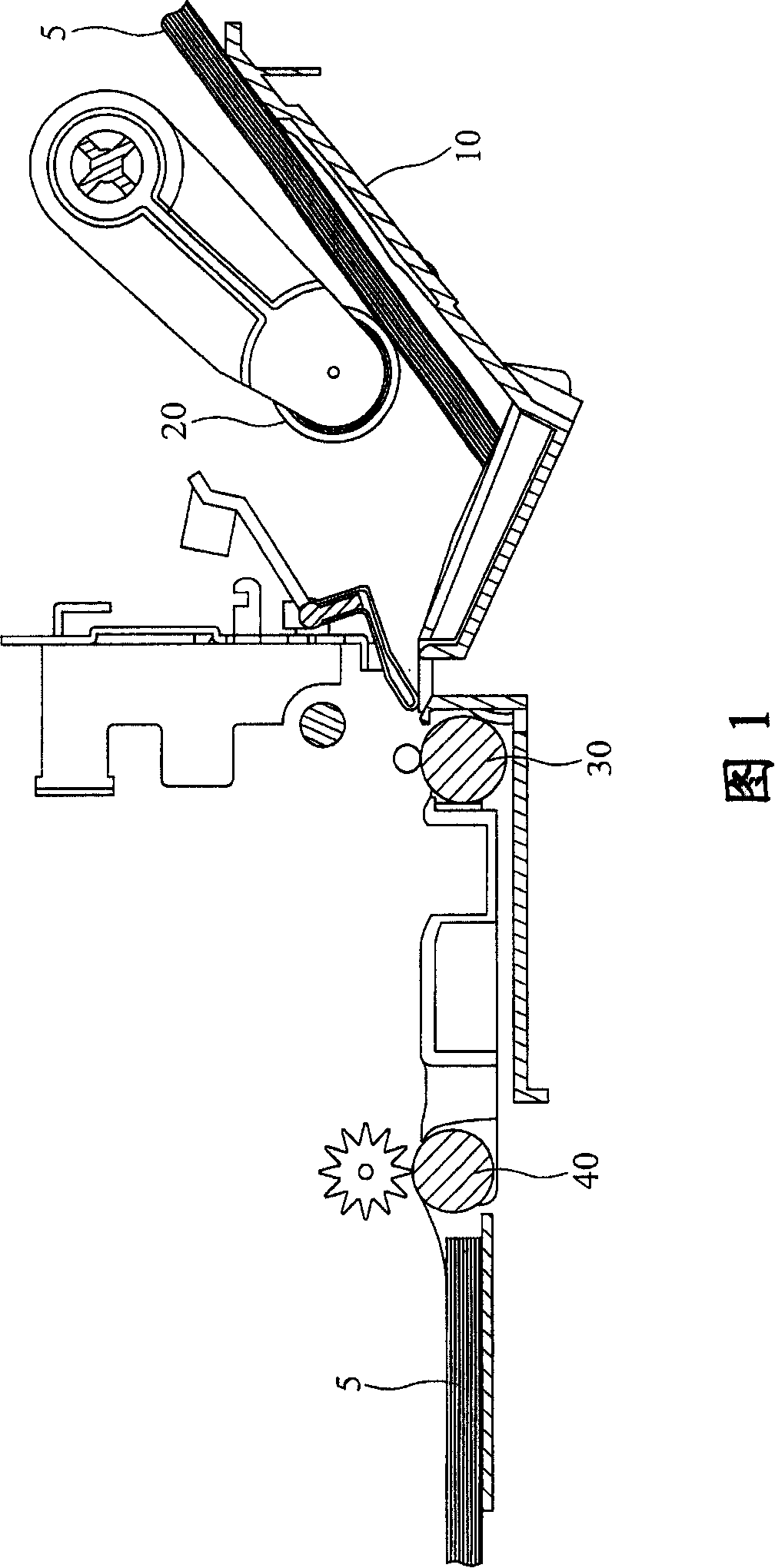
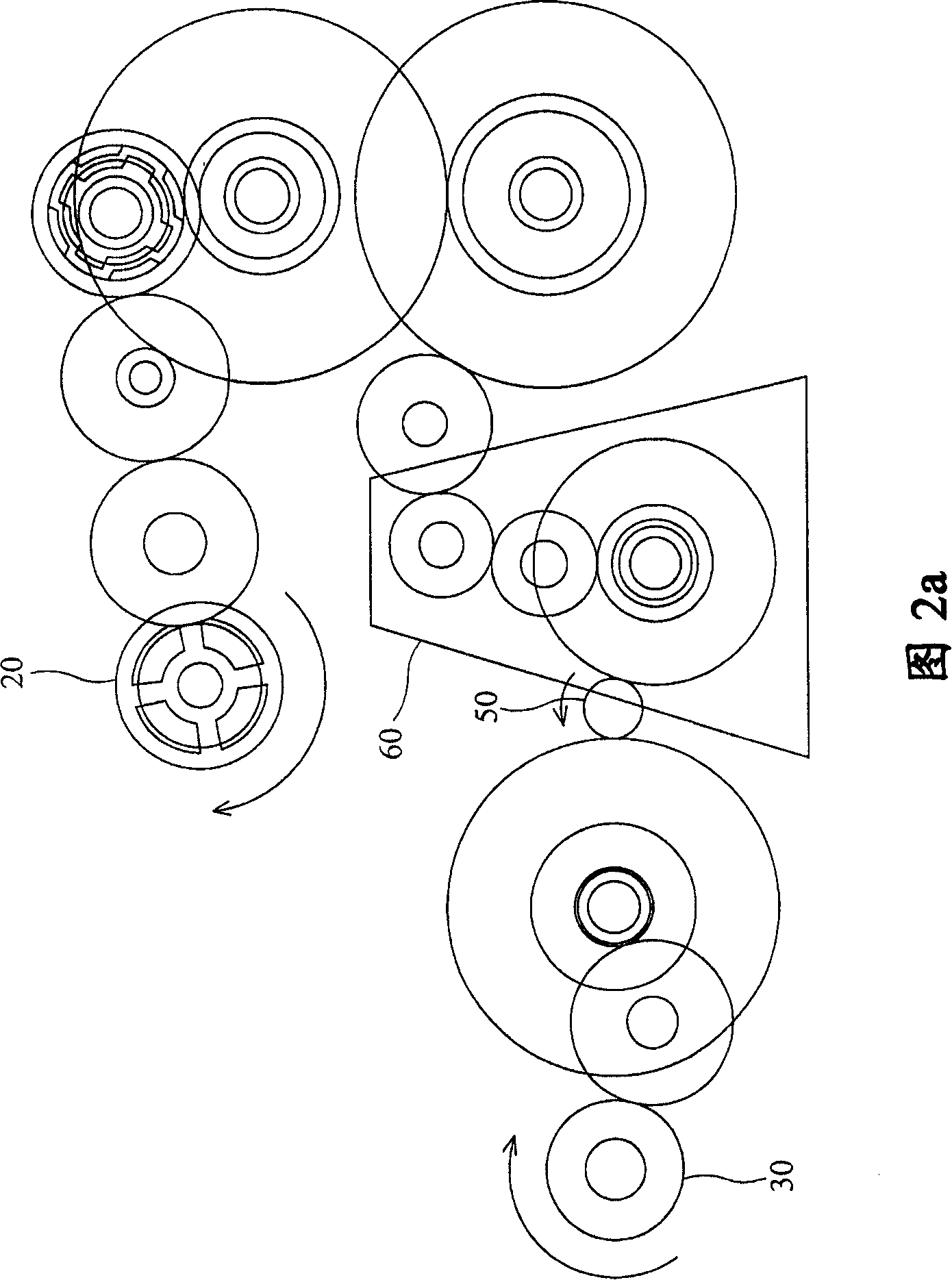
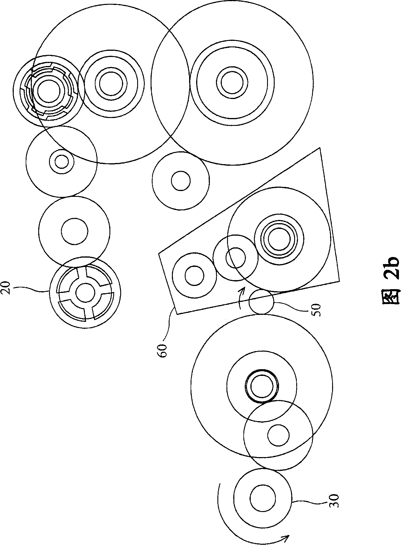
[0023] Fig. 3a is a perspective view of the paper output mechanism of the printer of the present invention, and Fig. 3b is an enlarged view of part A in Fig. 3a. Figure 4 is an exploded view of Figure 3a. The printer 1000 of the present invention includes a body 100, a paper discharge roller 200, and a paper pushing mechanism 300. When the paper discharge roller 200 rotates, paper (not shown) leaves the body from the body 100 in the paper discharge direction shown by arrow D 100.

[0024] As shown in FIG. 4 , the paper output roller 200 includes a shaft portion 210 and a roller portion 220 . The shaft part 210 is rotatably arranged on the body 100, and the roller part 220 is a cylinder with a larger diameter than the shaft part 210. It is arranged on the periphery of the shaft part 210 and is coaxial with the shaft part 210. , the roller part 220 will also rotate to push the paper toward the paper output direction D.

[0025] In order to ensure that the paper can be pushed ...


PUM


Abstract

The invention provides a paper-forcing mechanism in a paper delivery roller and a printer provided with the paper-forcing mechanism. The paper-forcing mechanism comprises a paper- forcing part, a cam and an elastic component. The invention is characterized in that the paper-forcing mechanism is combined with a shaft, with the rotating of the paper delivery roller, the mechanism moves intermittently toward the paper delivery direction to force the printed paper and enables the paper to depart from the paper delivery roller. The printer comprises a body, a paper delivery roller and at least a paper-forcing mechanism.

Description

technical field [0001] The present invention relates to a printer, in particular to a printer provided with a paper pushing mechanism. Background technique [0002] FIG. 1 is a schematic diagram of the structure of a conventional printer with an automatic sheet feeder (Auto Sheet Feed, ASF). In Fig. 1, the paper 5 on the paper holder 10 is drawn into the printer via a pick-up roller 20 for printing, and the printed paper passes through a feed roller 30 and a paper exit roller. ) 40 conveyed and discharged to the outside of the printer. The feed roller 30 and the paper discharge roller 40 are connected by a timing belt (not shown) to rotate synchronously and in the same direction. [0003] Figures 2a and 2b show the relationship between the feed roller 30 and the pickup roller 20. The pickup roller 20 and the feed roller 30 are driven by the same motor 50, but the pickup roller 20 is connected or separated from the motor 50 by means of the ASF clutch 60. . In the paper pi...

Claims


Application Information

Patent Timeline
IPC IPC(8): B65H29/00B65H29/20
Inventor 朱颖奇
Owner QISDA SUZHOU
Why Eureka
Try Eureka