Supercharge Your Innovation With Domain-Expert AI Agents!

Turbojet engine mounting structure for aircraft

一种涡轮喷气、发动机的技术,应用在喷气式动力装置、旋翼机、飞行器等方向,能够解决增加燃料消耗、涡轮喷气发动机效率损失、阻力等问题,达到简化设计的效果

Inactive Publication Date: 2008-05-14
AIRBUS OPERATIONS (SAS)
View PDF0 Cites 7 Cited by
  • Summary
  • Abstract
  • Description
  • Claims
  • Application Information

AI Technical Summary

Problems solved by technology

[0008] Thus, in the particular case in which a caisson-shaped pylon of large dimensions is arranged close to the central casing of the turbojet, this pylon inevitably induces a (fan) secondary flow (fan) flux escaping from the fan annular duct. secondaire), which directly leads to greater drag, loss of turbojet engine efficiency and increased fuel consumption

Method used


Image

  • Turbojet engine mounting structure for aircraft
  • Turbojet engine mounting structure for aircraft
  • Turbojet engine mounting structure for aircraft

Examples


Embodiment Construction

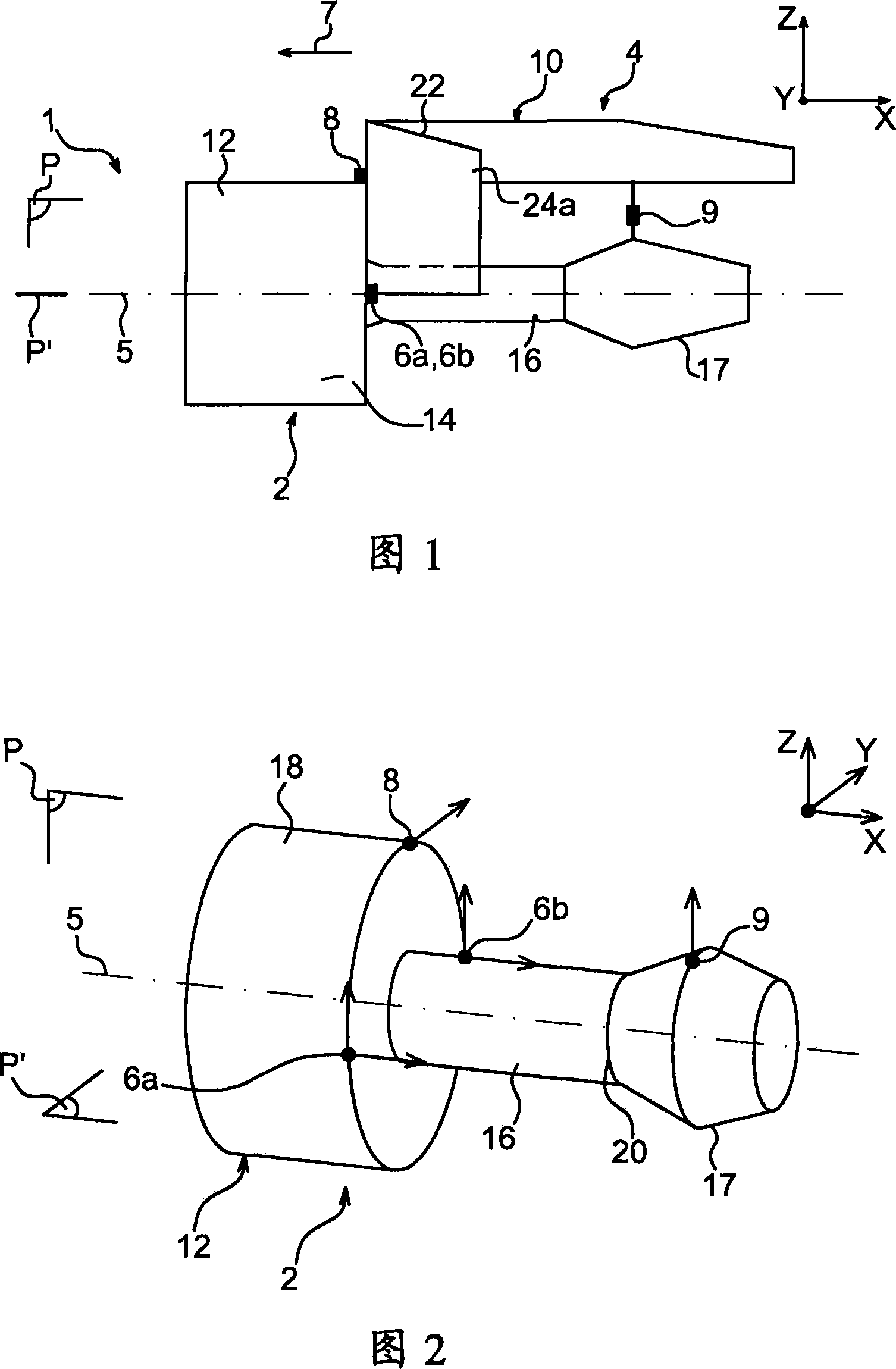
[0047] As shown in FIG. 1 , there can be seen an aircraft engine assembly 1 intended to be fixed under the wing of the aircraft (not shown), comprising an engine pylon 4 according to a first preferred embodiment of the invention.

[0048] In general, an engine assembly 1 comprises a turbojet engine 2 and a pylon 4 equipped in particular with a plurality of engine attachments 6a, 6b, 8, 9 and a rigid structure 10 to which these attachments are fixed (in Attachment 6b is covered by attachment 6a on Fig. 1). Indicatively, it is worth noting that the assembly 1 is intended to be surrounded by a nacelle (not shown), and that the pylon 4 comprises a further series of attachments (not shown) for ensuring that the assembly 1 is suspended under the wing of the aircraft.

[0049] In all the ensuing elaborations, the longitudinal direction of the pylon 4 is called X, which is also similar to the longitudinal direction of the turbojet 2 , which is parallel to the longitudinal axis 5 of th...


PUM


Abstract

The invention relates to an aircraft jet engine pylon suspension attachment comprising a rigid structure (10) provided with a central longitudinal caisson (22). According to said invention, the rigid structure also comprises two side caissons (24a, 24b) fixed to the front part of the central caisson (22), the pylon is provided with first (6a) and second (6b) front engine fasteners which are constructed in such a way that they pick up loads produced in the longitudinal direction (X) of the pylon, wherein said first and second fasteners are connected to the two side caissons, respectively.

Description

technical field [0001] The invention relates generally to turbojet pylons for aircraft. This type of pylon, also known as EMS (Engine Mount Structure), can be used to suspend a turbojet engine on the underside of an aircraft wing, or preferably mount it on top of the same wing. Background technique [0002] Such a hanger ( d'accrochage) are designed to form the connection interface between the turbojet engine and the wing of the aircraft. The pylon transmits the forces generated by the associated turbojet engines of the aircraft to the structure of the aircraft and also allows the passage of fuel, electrical systems, hydraulic systems and air between the engines and the aircraft. In order to ensure the transmission of force, the hanger ( ) generally comprise a rigid structure of the "caisson" type, ie a rigid structure constituted by the assembly of upper beams, lower beams and side plates interconnected by means of transverse ribs. [0003] On the other hand, the pylo...

Claims


Application Information

Patent Timeline
Patent Type & Authority Applications(China)
IPC IPC(8): B64C27/18B64D27/40
CPCB64D27/18
Inventor 利昂内尔·迪奥雄迈克尔·萨拉托戴维·沙尔捷伊莎贝尔·彼得里桑
Owner AIRBUS OPERATIONS (SAS)
Features
  • R&D
  • Intellectual Property
  • Life Sciences
  • Materials
  • Tech Scout
  • Unparalleled Data Quality
  • Higher Quality Content
  • 60% Fewer Hallucinations
Learn More