Method for online real-time removing oscillation error of optical fibre gyroscope SINS system

A technology of fiber optic gyroscope and oscillation error, which is applied in the direction of navigation through speed/acceleration measurement, and can solve the problems of reduced system reliability, reduced system autonomy, and oscillation error of the fiber optic gyroscope strapdown inertial navigation system.

Inactive Publication Date: 2008-05-21
HARBIN ENG UNIV
View PDF0 Cites 16 Cited by
  • Summary
  • Abstract
  • Description
  • Claims
  • Application Information

AI Technical Summary

Problems solved by technology

[0005] The purpose of the present invention is to solve the problem that the existing method of improving the navigation accuracy of the fiber optic gyro strapdown inertial navigation system will not only increase the cost of the

Method used


Image

  • Method for online real-time removing oscillation error of optical fibre gyroscope SINS system
  • Method for online real-time removing oscillation error of optical fibre gyroscope SINS system
  • Method for online real-time removing oscillation error of optical fibre gyroscope SINS system

Examples


specific Embodiment approach 1

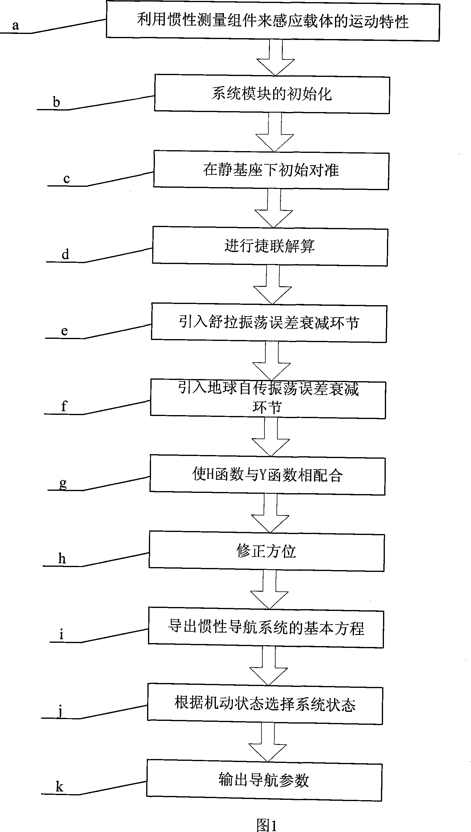
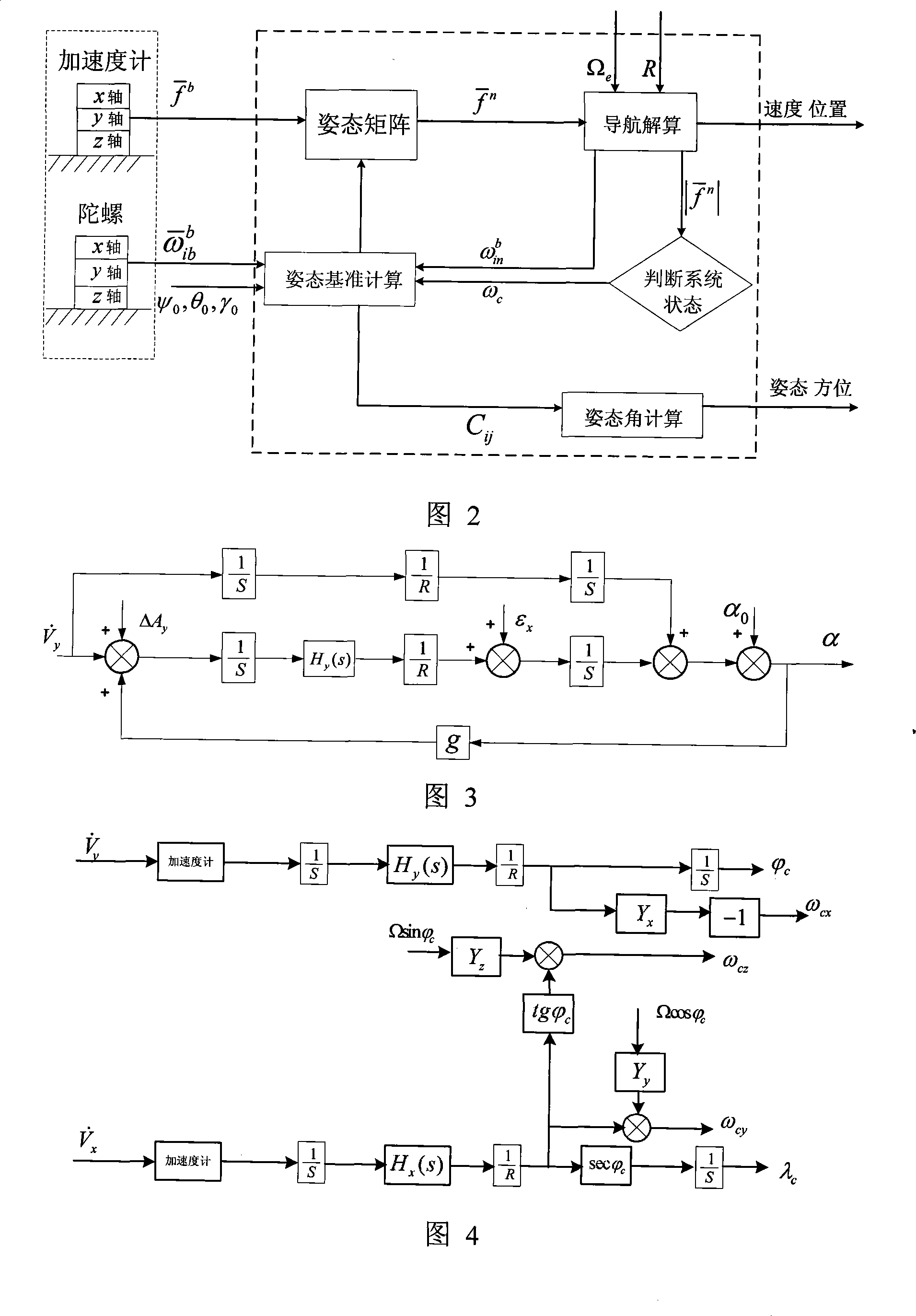
[0037] Specific embodiment one: referring to Fig. 1, Fig. 2 and Fig. 4, the hardware composition of the strapdown inertial navigation system in this embodiment is the same as that of the traditional strapdown inertial navigation system, and the specific method includes the following steps:

[0038] Step a, using an inertial measurement component (inertial measurement component) composed of a fiber optic gyroscope with three degrees of freedom and a quartz accelerometer with three degrees of freedom to sense the motion characteristics of the carrier: the inertial measurement component is sensitive to the movement of the carrier along its axis through the fiber optic gyroscope Angular velocity signal, the linear acceleration signal along the axis of the carrier is measured by the accelerometer, and the signal is transmitted to the computer;

[0039] Step b. Initialization of system modules: the fiber optic gyro strapdown inertial navigation system should generally be started unde...

specific Embodiment approach 2

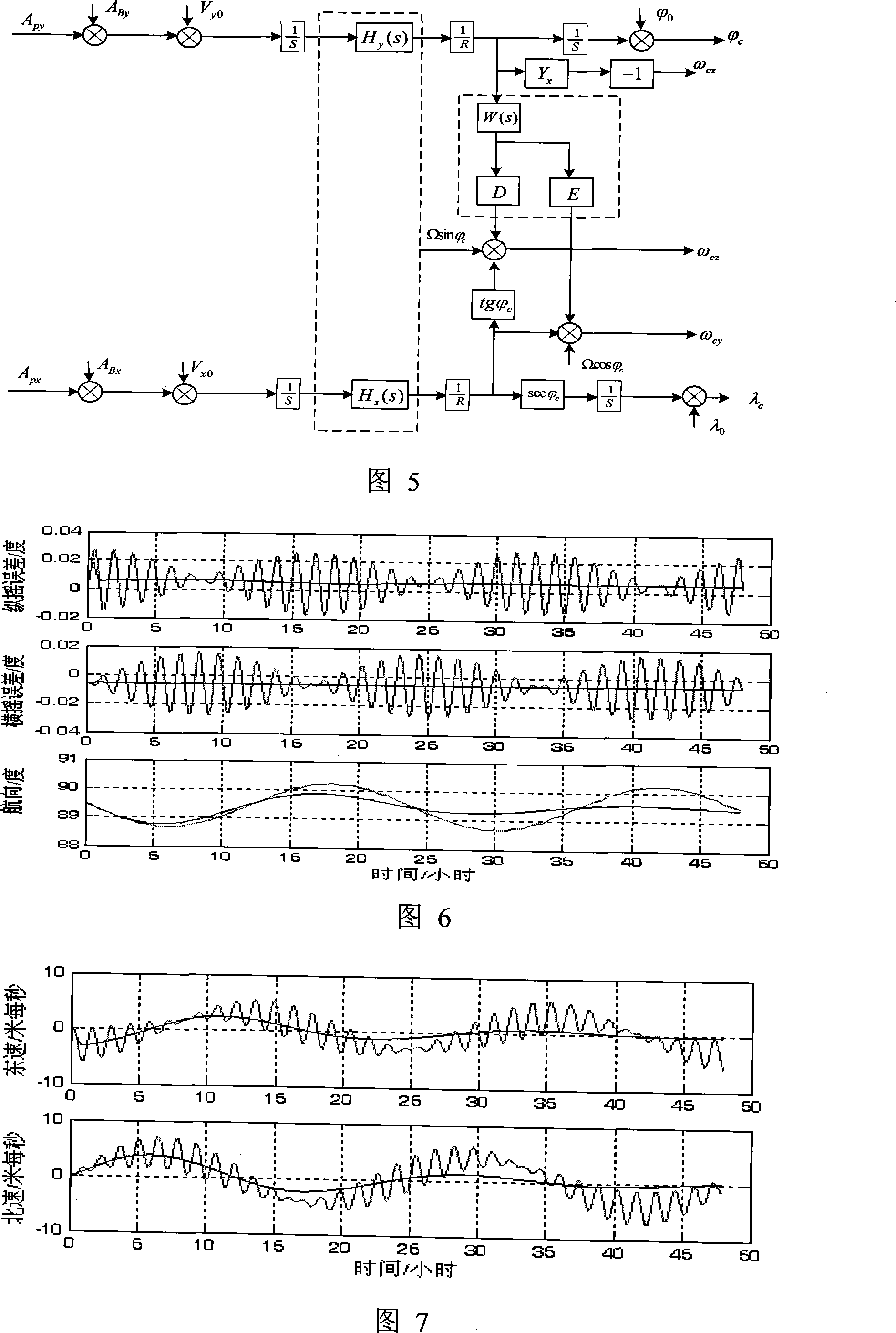
[0073] Specific embodiment two: see Figure 5, according to specific embodiment one, for better simplification

[0074] ω x = - Y x V cy R M H y

[0075] For the convenience of structure and use, the formula in step f Simplified to the following form:

[0076]

[0077] Order Y x (s)=Y y (s)=Y z (s), W = Ω s ( 1 - Y ) ,

[0078] ω x = - V cy R M H y

[0079] Then there are:

[0080]

specific Embodiment approach 3

[0081] Specific embodiment three: Referring to Fig. 3, the difference between this embodiment and specific embodiment one is that in step e, in the Shura circuit of the single-channel northward horizontal circuit, after the first integrator, before the second integrator, a series connection is added. The oscillation error attenuation link H y (s), when H y When (s)=1, the strapdown inertial navigation system is in an undamped state. At this time, the acceleration and velocity have no effect on the horizontal error angle, but other disturbances will produce an oscillating error component on the horizontal error angle, with a period of 84.4 minutes , that is, the Shura period oscillation, when H y When (s) is not 1, the horizontal inclination oscillation error generated by various disturbances will gradually attenuate, but for the error component of the navigation parameters generated by acceleration and velocity, what we hope is to add this link to make the oscillation The er...


PUM


Abstract

The invention provides an online method which can eliminate the oscillation error of a fiber optic gyroscope strap-down inertial navigation system in real time and relates to an error compensation method of a strap-down inertial navigation system, moreover, the method belongs to the technical field of strap-down inertial navigation technology and data process. The invention aims at solving the shortcoming of the prior method of improving the navigation accuracy of the fiber optic gyroscope strap-down inertial navigation system which leads to increasing the system cost and decreasing reliability and system autonomy, etc. The method of the invention comprises the following steps: step a, an inertial measuring component is adopted to sense kinetic characteristics of the carrier; step b, the system module is initialized; step c, initial adjustment is conducted; step d, strap-down solving is conducted; step e, a sula oscillation error decay link is drawn into the invention; step f, an earth rotation oscillation error decay link is drawn into the invention; step g, the invention results in that Y function is compatible with H function; step h, orientation is revised; step i, the basic mathematical equation of the inertial navigation system is derived from the invention; step j, the system state is selected according to the flexible state; step k, the navigation parameter is output.

Description

technical field [0001] The invention relates to an error compensation method for a strapdown inertial navigation system, and belongs to the technical fields of strapdown inertial navigation technology and data processing. Background technique: [0002] The fiber optic gyroscope strapdown inertial navigation system (Strap-down Inertial Navigation System referred to as optical SINS) is based on the law of inertia, using the fiber optic gyroscope and accelerometer to feel the carrier's rotational angular rate and specific force relative to the inertial space, through the computer After the corresponding coordinate transformation, the integral operation is carried out to obtain the navigation parameters such as the attitude, speed and position of the carrier. Strapdown inertial navigation system is an autonomous navigation system with low cost, simple structure and good reliability. In an undamped strapdown inertial navigation system, the attitude, heading and velocity errors c...

Claims


Application Information

Patent Timeline
IPC IPC(8): G01C21/18
Inventor 孙枫徐博高伟周广涛陈世同程建华吴磊于强高洪涛
Owner HARBIN ENG UNIV
Why Eureka
Try Eureka