
Leather and leather manufacturing method

A technology of leather and raw materials, applied to leather, steering controls and control devices mounted on cars, etc., can solve the problems of steering wheel appearance deterioration, deterioration, fingertip stuck feel, etc.

Active Publication Date: 2008-05-21
MIDORI ANZEN
View PDF1 Cites 5 Cited by
  • Summary
  • Abstract
  • Description
  • Claims
  • Application Information

AI Technical Summary

Problems solved by technology

[0011] And, if the amount of turning back is larger than the design value, the overlapping portion 202 is formed in a state in which the turning portion is extruded as shown in FIG.
[0012] In this way, if the overlapping portion 202 is formed in an inaccurate shape, the overall shape of the leather 200 becomes inaccurate, and when it is adhered to the core material of the steering wheel, a gap occurs between the leathers or the leathers overlap each other. The appearance of the steering wheel is deteriorated, and unnecessary catching parts are formed, so that the fingertips are caught, etc., and the feel is also deteriorated
The steering wheel including these problems is a part for automobiles as described below, and since there is a problem in the part where the driver directly touches the hand, it becomes an obstacle to the safe operation of the vehicle and cannot be a finished product.
[0013] In addition, the above-mentioned problems occur not only on the steering wheel, but also on the leather used for the shift handle or the leather that has not been stitched.

Method used


Image

  • Leather and leather manufacturing method
  • Leather and leather manufacturing method
  • Leather and leather manufacturing method

Examples


no. 1 approach

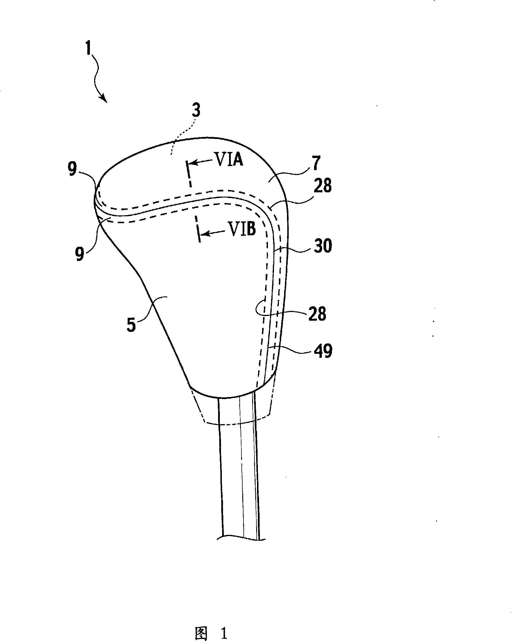
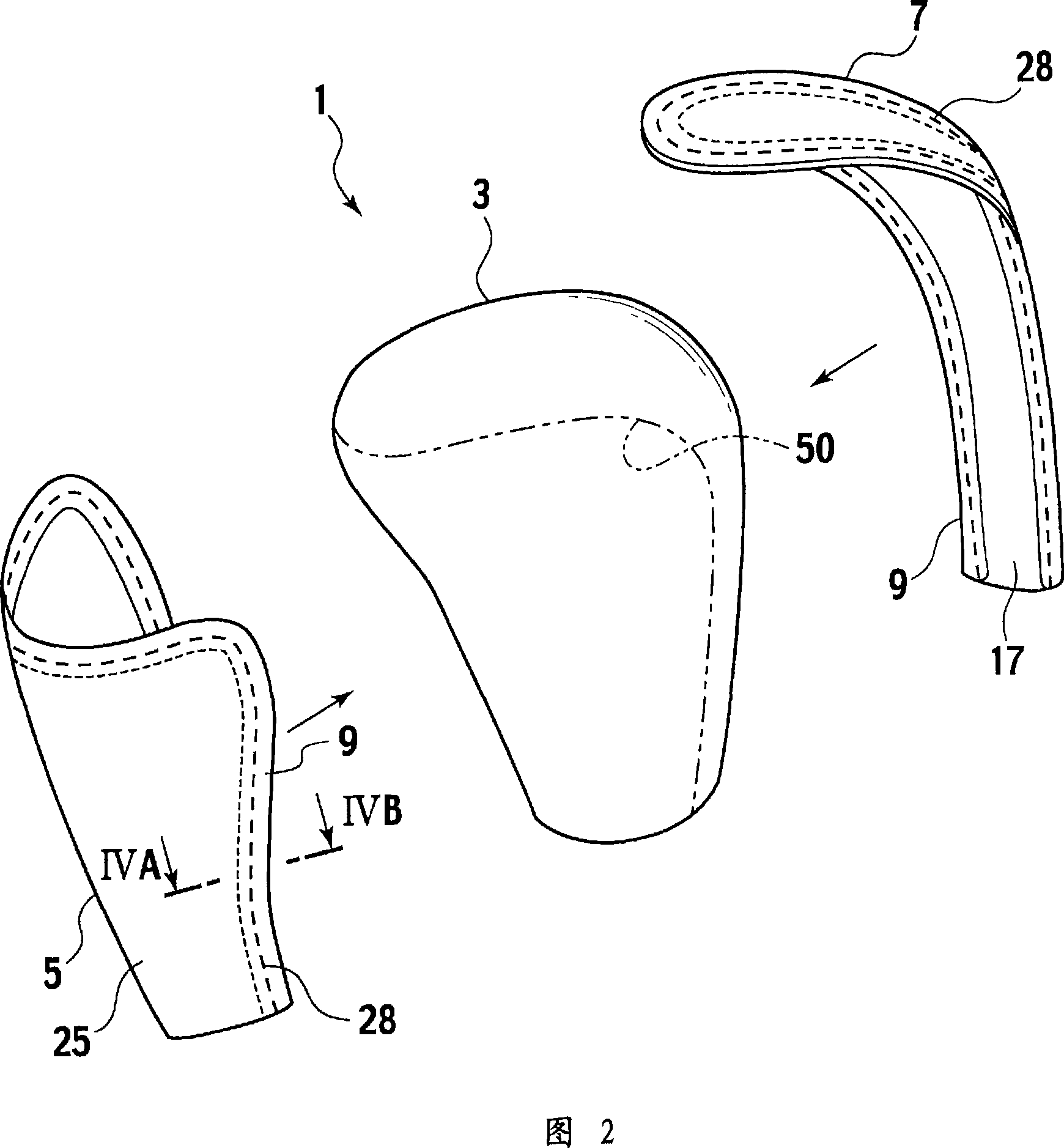
[0040] Fig. 1 is a diagram showing a schematic configuration of a shift lever 1 according to a first embodiment of the present invention, and Fig. 2 is a diagram showing a state in which the shift lever 1 is disassembled.

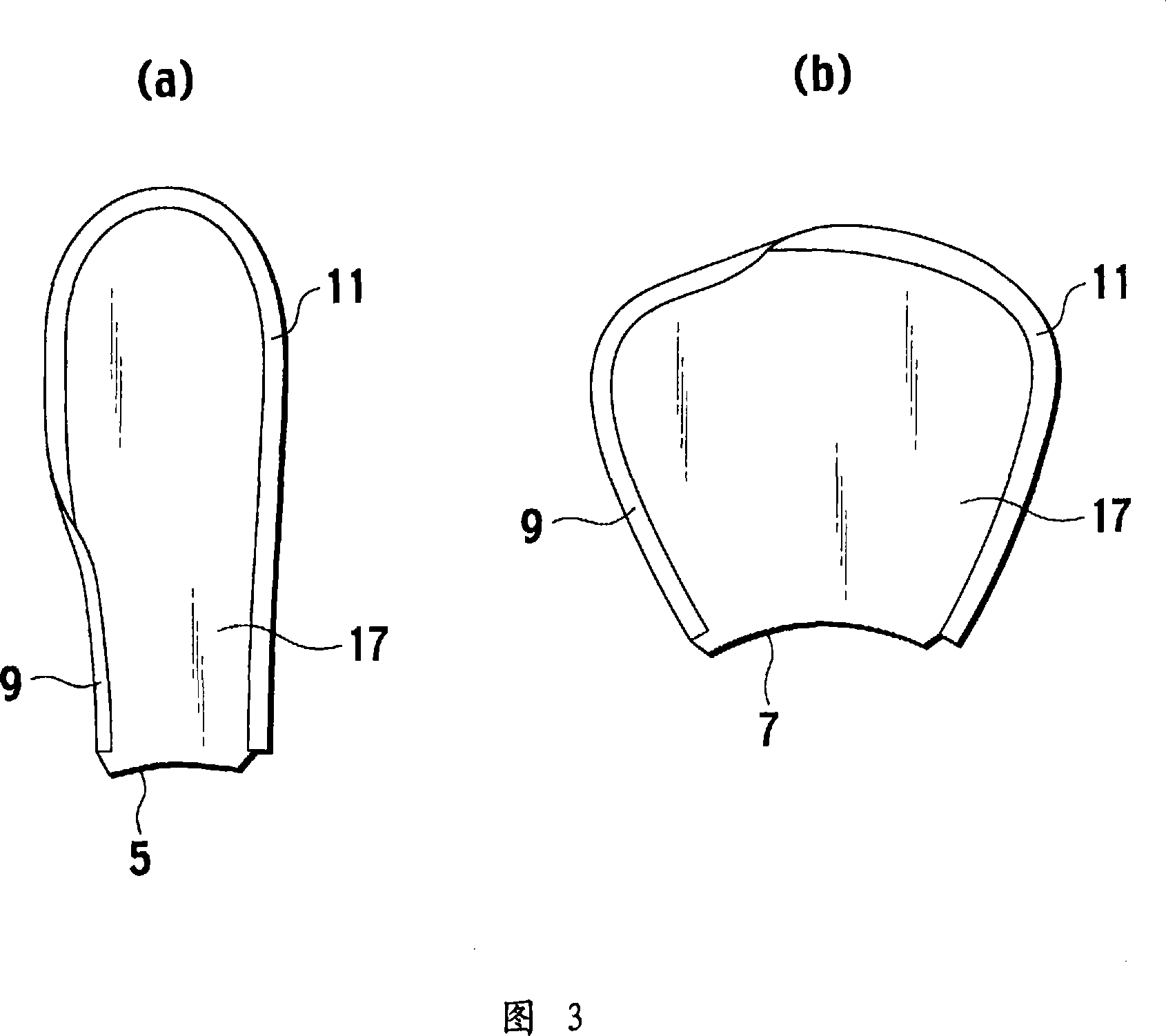
[0041] The shift lever 1 is, for example, a member used for being attached to the front end of a shift lever of a transmission of an automobile or a front end of an operating lever of a parking brake of an automobile, and has a core material (trunk) 3 constituting a main body, and the above-mentioned core material 3 Cover with leather 5 and leather 7. Moreover, the above-mentioned core material 3 is formed using the existing technology. That is, the core material 3 covers the core shaft with resin such as urethane resin, and the core shaft and the urethane resin are integrally formed.

[0042] In more detail, in a state where the end edges of the leathers 5 and 7 are butted (in contact), the backs of the leathers 5 and 7 (the core material 3 side of the leather...


PUM


Abstract

In the leather (5) used to cover the shift handle (1), at the small rigid part with small bending rigidity formed along the end edge (21) of the leather material (20), the back side of the leather material (20) The leather material (20) is folded back in contact with each other to form an overlapping portion (9).

Description

Technical field [0001] The present invention relates to leather, and particularly relates to leather having an overlapped portion formed on the edge. Background technique [0002] Fig. 19 is a perspective view showing a schematic structure of a conventional leather 200. [0003] The existing leather 200 is used to cover a steering wheel, for example, and has an overlapping portion 202. The overlapping portion 202 is formed as follows. A thin-walled portion 208 of a predetermined width is formed on the side of the end edge 206 of the leather material 204, and stitches (not shown) are sewn on the thin-walled portion 208 with a certain distance from the end edge 206. (For example, half the width of the thin-walled portion 208) is formed by folding the thin-walled portion 208 back and bonding (for example, refer to Japanese Patent Laid-Open No. 6-64546). [0004] Furthermore, the leather 200 on which the overlap portion 202 is formed is adhered to the core material of the steering wh...

Claims


Application Information

Patent Timeline
Patent Type & Authority Applications(China)
IPC IPC(8): B62D1/06B60K20/02B68F1/00D06N3/00
CPCB62D1/06B68F1/00Y10T74/2087Y10T74/20876Y10T428/2419
Inventor 有马隆小林圣一铃木智之
Owner MIDORI ANZEN
Learn More