LED spotlight

A technology of LED floodlights and light-emitting boards, which is applied in the direction of light sources, electric light sources, point light sources, etc., can solve the problems of large and uniform light emitting angles, increased costs, and application restrictions, and achieve improved light projection effects and increased angles , the effect of increasing the irradiation area

Inactive Publication Date: 2008-05-28
NINGBO ANDY OPTOELECTRONIC CO LTD
View PDF0 Cites 17 Cited by
  • Summary
  • Abstract
  • Description
  • Claims
  • Application Information

AI Technical Summary

Problems solved by technology

[0002] LED has the advantages of environmental protection, energy saving, and long life, so it is regarded as a lighting source in the 21st century. However, LED has a specific luminous angle, which cannot be as large and uniform as traditional light sources, so its application is subject to certain restrictions.
see Figure 8 As shown, the existing LED floodlight usually installs a plurality of LED93 components on a plane circuit board 92. Since the LED has a specific light emitting angle, the light 931 emitted by the LED components arranged in a plane is basically in the direction perpendicular to the plane of the circuit board. As a result

Method used


Image

  • LED spotlight
  • LED spotlight
  • LED spotlight

Examples


Embodiment 1

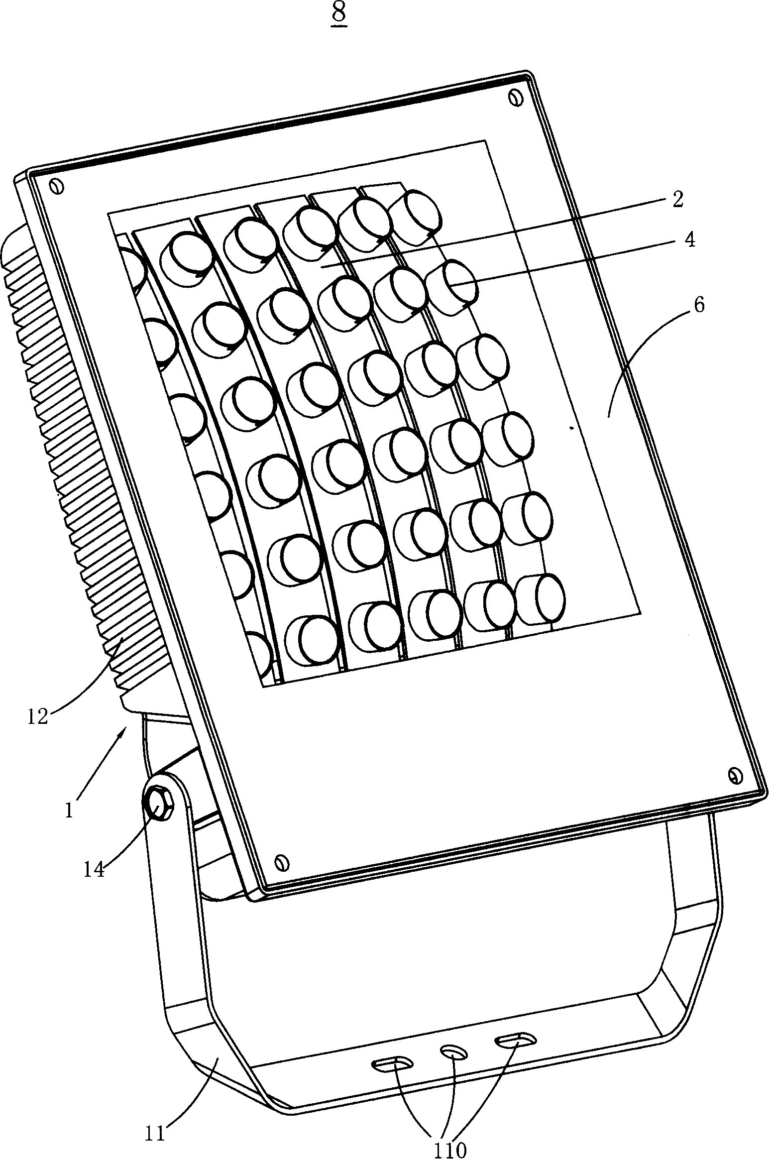
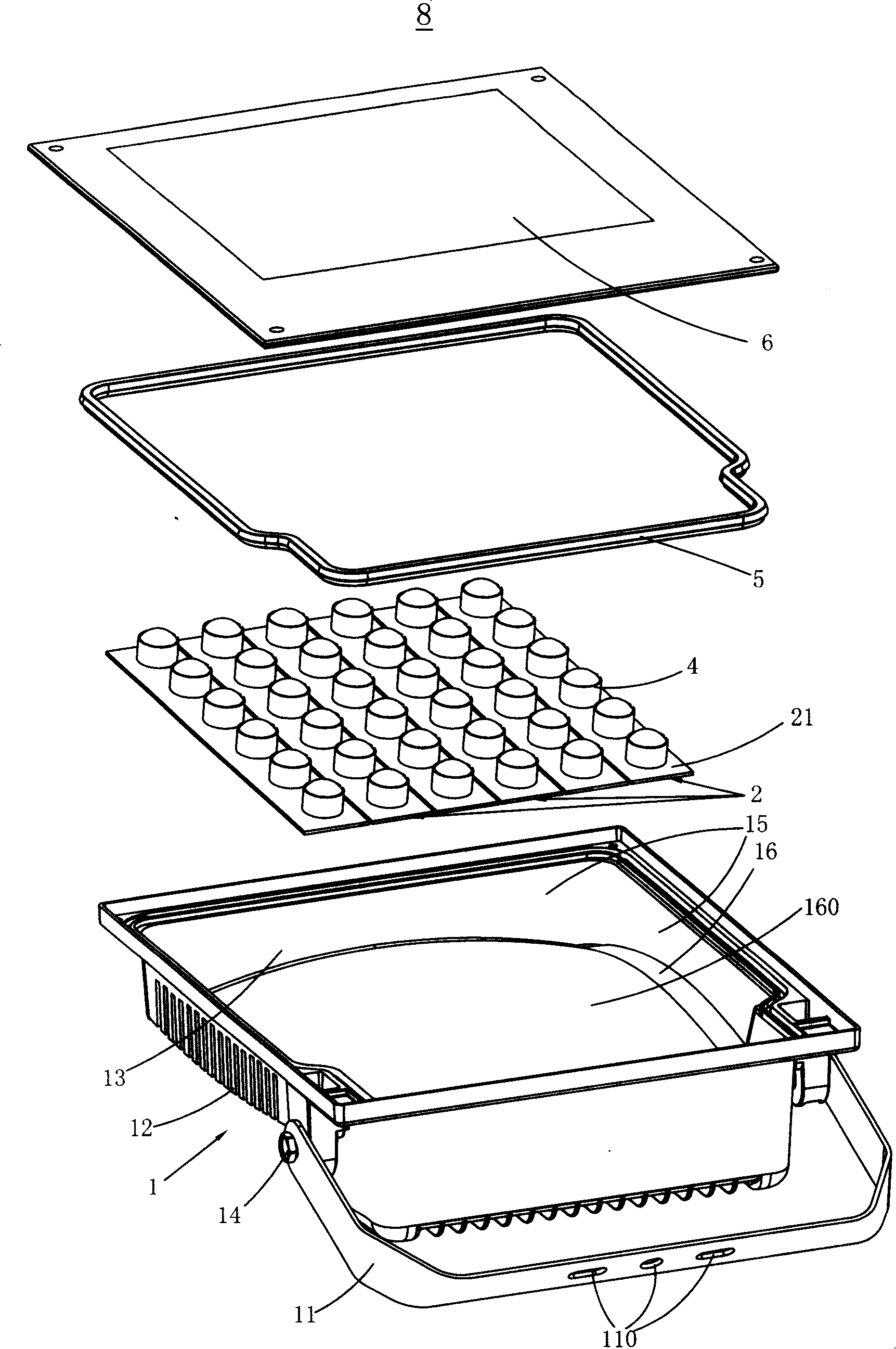
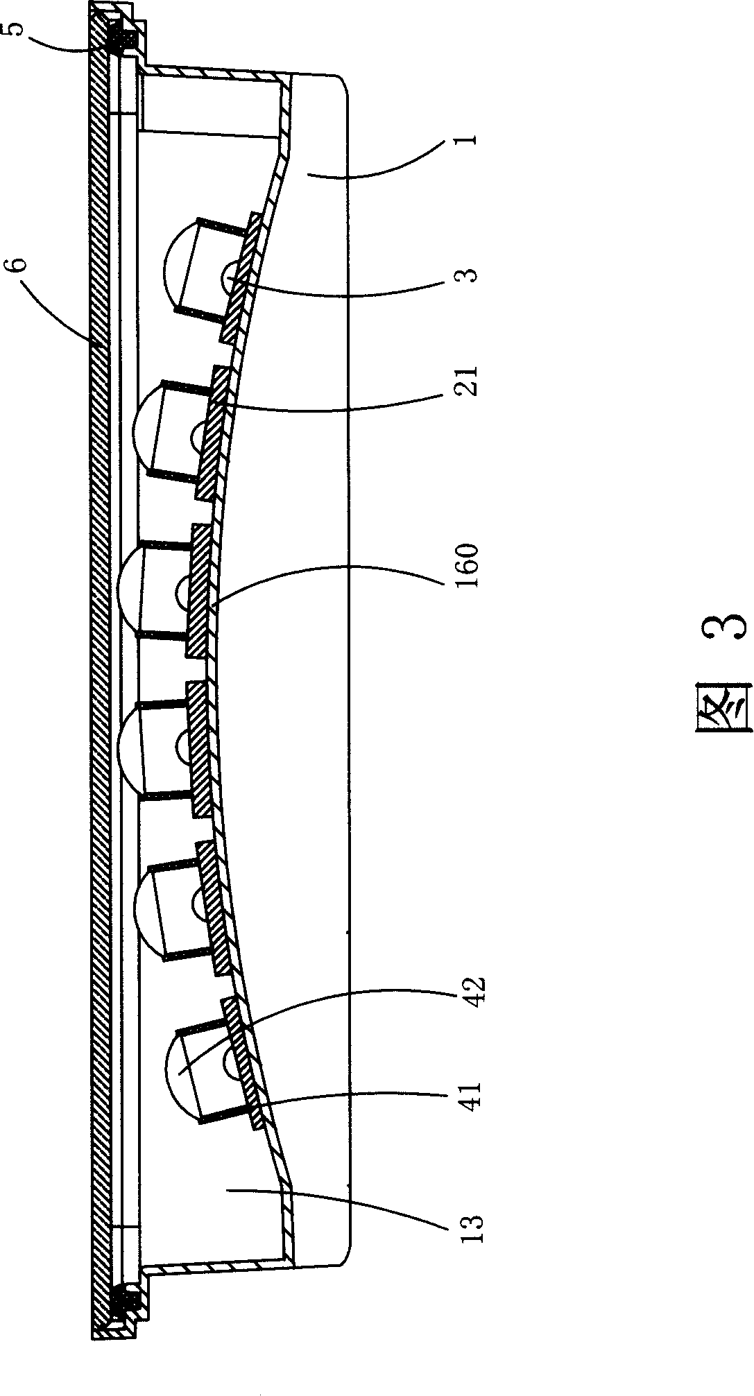
[0024] see figure 1 , figure 2 , Figure 3 and Figure 4 As shown, the floodlight 8 disclosed in this embodiment includes a housing 1, a circuit board 2, an LED 3, a lens unit 4, a sealing ring 5 and a light output plate 6, wherein the LED 3 is housed in the housing 1, The light-emitting plate 6 is fixed on the housing 1 and the LED 3 is enclosed in the housing 1. The LED 3 is arranged in a convex arc shape in the direction of the light-emitting plate 6 in the housing 1. The outer The central angle of the convex arc surface ranges from 10 degrees to 100 degrees, and the LED 3 is a high-power LED (in this embodiment, its power is greater than or equal to 1 watt).

[0025] The housing 1 is made of a material with good thermal conductivity (for example, aluminum), and the housing 1 includes a bottom wall 16, four side walls 15 and a receiving space surrounded by the bottom wall 16 and the side walls 15. 13. The center of the bottom wall 16 protrudes outward to form an arc-sh...

Embodiment 2

[0030] see Figure 6 As shown in FIG. 7 , the difference between the LED floodlight 8 ′ disclosed in this embodiment and the LED floodlight 8 disclosed in Embodiment 1 is that the arc-shaped base 160 ′ supporting the circuit board 2 ′ is not formed by the casing 1 'formed in one piece, but an additional arc-shaped base 160' for supporting the circuit board 2' is installed on the bottom wall 16' of the housing 1'. The bottom wall 16' of the housing 1' is a plane, and the arc-shaped base 160' is made of a material with good thermal conductivity, which is fixed on the bottom wall 16' by screws or other known methods. The circuit board 2' is mounted on the surface of the arc-shaped base 160' adjacent to the housing bottom wall 16', so that the LEDs 3' on the circuit board 2' are distributed in an arc along the surface of the arc-shaped base 160'. The light emitting board 6' is mounted on the housing 1' by means of screw connection, etc., and the circuit board 2', LED 3' and lens ...


PUM

PropertyMeasurementUnit
Central angleaaaaaaaaaa

Abstract

The invention discloses an LED projecting light (8), comprising a casing (1), a light outlet plate (6), and a plurality of LEDs (3), wherein the LEDs (3) are collected in the casing (1), the light outlet plate (6) is fixed on the casing (1) to seal the LEDs (3) in the casing (1), and the LEDs (3) are arranged in the casing (1) taking on external convex arc surface towards the direction of the light outlet plate (6). The invention enables the LED component 3 to be arranged in the LED projecting light (8) taking on external convex arc surface through arranging an arc-shaped base body (160) in the LED projecting light (8), enables the lighting angle of the LED projecting light (8) to be greatly enlarged under the condition of enlarging the volume of the current LED projecting light, thereby increasing the light area of the LED projecting light (8), and further effectively improving the projecting effect of the LED projecting light (8) under the condition of no increasing costs.

Description

【Technical field】 [0001] The present invention relates to an LED floodlight, more precisely, to an LED floodlight with better light projection effect. 【Background technique】 [0002] LED has the advantages of environmental protection, energy saving, and long life, so it is regarded as a lighting source in the 21st century. However, LED has a specific luminous angle, which cannot be as large and uniform as traditional light sources, so its application is limited. see Figure 8 As shown, the existing LED floodlight usually installs a plurality of LED93 components on a plane circuit board 92. Since the LED has a specific light emitting angle, the light 931 emitted by the LED components arranged in a plane is basically in the direction perpendicular to the plane of the circuit board. As a result, the light spot L1 formed in front of it is small, that is to say, the irradiation angle of the LED floodlight is not large, which causes the problem that its light projection effect can...

Claims


Application Information

Patent Timeline
IPC IPC(8): F21S4/00F21V23/00F21V5/04F21V29/00F21Y101/02F21K9/20F21V29/503F21V29/74F21Y115/10
Inventor 刘学勇楼红献
Owner NINGBO ANDY OPTOELECTRONIC CO LTD
Why Eureka
Try Eureka