Sealing device
A sealing device and sealing component technology, applied in the direction of engine sealing, bearing components, engine components, etc., can solve problems such as insufficient sealing performance, and achieve the effect of improving sealing performance and inhibiting the intrusion of foreign objects such as mud and water.
- Summary
- Abstract
- Description
- Claims
- Application Information
AI Technical Summary
Problems solved by technology
Method used
Image
Examples
no. 1 example
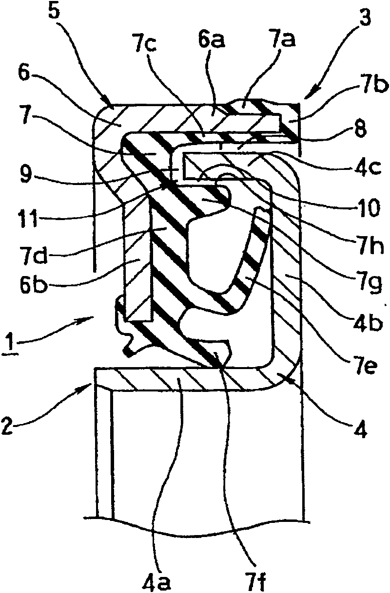
[0055] figure 1 This is a sectional view showing a main part of the sealing device 1 according to the first embodiment of the present invention. The sealing device 1 described in this embodiment is used for hub bearing seals (bearing pad seals) in the field of automobiles, and has the following structure. This embodiment is the embodiment described in relation to claim 1 of the present application.
[0056] That is, firstly, the sealing device 1 has an inner circumference mounted on a bearing inner ring (inner peripheral side mounting part, not shown in the figure) as one side member of the two relative rotation members, and rotates together with the bearing inner ring. A side seal member 2, and a non-rotating outer peripheral side seal member 3 mounted on the other side of the two parts, that is, the bearing outer ring (outer peripheral side mounting part, not shown in the figure).
[0057] The inner peripheral side seal member 2 is composed of an oil slinger member (herei...
no. 2 example
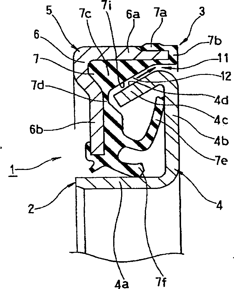
[0066] figure 2 A cross-sectional view showing a main part of the sealing device 1 according to the second embodiment of the present invention. The sealing device 1 described in this embodiment is used for hub bearing seals (bearing pad seals) in the related automotive field, and its structure is as follows. This embodiment is related to the embodiment related to claim 2 of the present application.
[0067] That is, first, this sealing device 1 has an inner bearing inner ring (an inner peripheral side mounting member, not shown in the figure) which is one side member of two parts which rotate relatively, and which rotates together with the bearing inner ring. The peripheral side sealing member 2, and the non-rotating outer peripheral side sealing member 3 installed on the bearing outer ring (outer peripheral side mounting part, not shown in the figure) of the other part of the two parts.
[0068] The inner peripheral side seal member 2 is constituted by an oil slinger membe...
no. 3 example
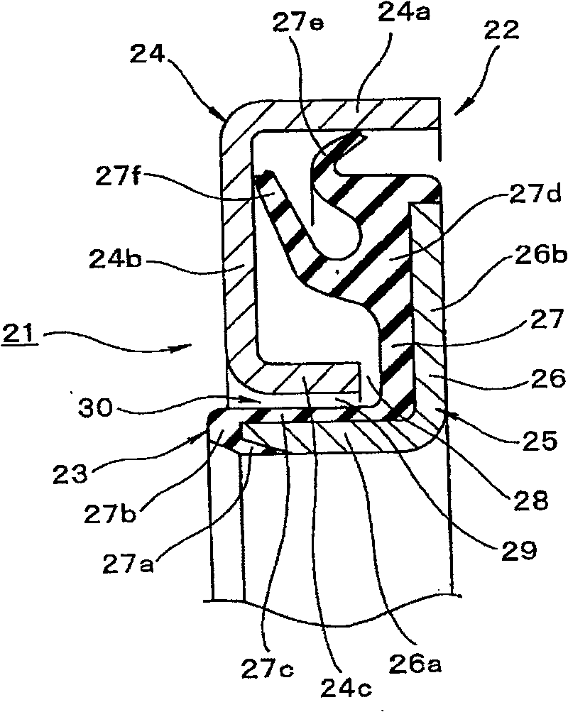
[0078] image 3 A sectional view showing a main part of a sealing device 21 according to a third embodiment of the present invention. The sealing device 21 described in this embodiment is used for hub bearing seals (pad seals) in the field of automobiles, and has the following structure. This embodiment is related to the embodiment related to claim 3 of the present application.
[0079] That is, firstly, the sealing device 21 has an outer peripheral side sealing member 22 which is mounted on the bearing outer ring (outer peripheral side mounting part, not shown in the figure) as one side part of the two parts which rotate relatively, and which does not rotate and a mounting part. The inner peripheral side sealing member 23 is on the other side of the two parts, that is, the bearing inner ring (outer peripheral side mounting part, not shown in the figure) and rotates together with the bearing inner ring.
[0080] The outer peripheral side sealing member 22 is constituted by a...
PUM
 Abstract
Description
Claims
Application Information
 - R&D
- Intellectual Property
- Life Sciences
- Materials
- Tech Scout
- Unparalleled Data Quality
- Higher Quality Content
- 60% Fewer Hallucinations
Browse by: Latest US Patents, China's latest patents, Technical Efficacy Thesaurus, Application Domain, Technology Topic, Popular Technical Reports.
© 2025 PatSnap. All rights reserved.Legal|Privacy policy|Modern Slavery Act Transparency Statement|Sitemap|About US| Contact US: help@patsnap.com


