Image display, image displaying method and order input method
An image display device, image technology, applied in the direction of digital output to display device, input/output process of data processing, modification/creation of images using manual input, etc., can solve problems such as impossible
- Summary
- Abstract
- Description
- Claims
- Application Information
AI Technical Summary
Problems solved by technology
Method used
Image
Examples
no. 1 example
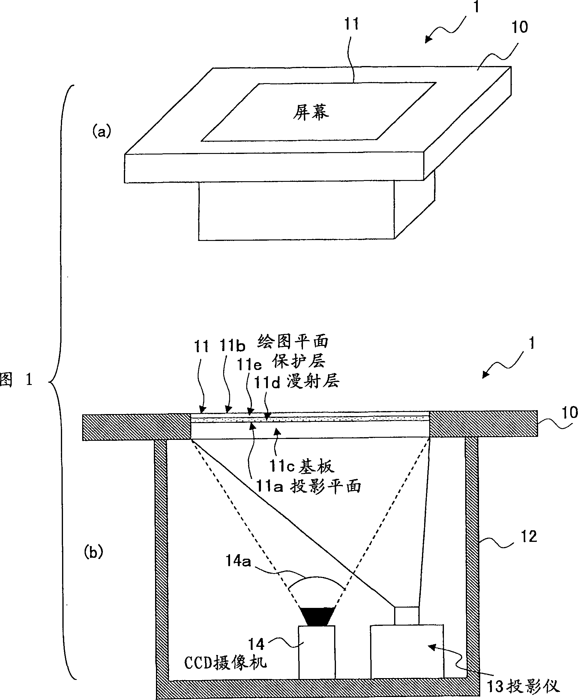
[0087] 1-(a) and (b) show schematic views of an embodiment of an image display device according to the present invention.
[0088] Fig. 1-(a) shows a schematic perspective view, and Fig. 1-(b) shows a schematic cross-sectional view.
[0089] As shown in FIG. 1 , the image display device of the embodiment has a rectangular planar unit 10 including a table-like display unit 1 and a main body unit 2 not shown in the figure.
[0090] The display unit 1 includes a rectangular screen 11 (corresponding to the display screen according to the present invention) at the central portion of the plane unit 10, on which an image projected from the inside thereof is displayed.
[0091] In addition, as shown in FIG. 1-(b), the display unit 1 of the image display device includes a plane unit 10 having a screen 11 embedded in a central portion; a housing 12 for supporting the plane unit 10; a projector 13 arranged Inside the housing 12, a projector 13 projects an image on a screen 11; a CCD cam...
no. 2 example
[0270] The identification code provided to the bottom of the object in the first embodiment is formed to have a unique pattern in consideration of the rotation of the object. However, such identification codes have the following problems:
[0271](i) The shape of the identification code must be registered for each rotation angle in the dictionary because the code pattern changes according to the rotation angle of the object,
[0272] (ii) the number of identification codes that can be registered is limited because the identification codes must be unique taking into account the rotation of the object, and
[0273] (iii) The entire area of the bottom of the object must be scanned to identify the object.
[0274] Because of this, in the second embodiment, a circular one-dimensional barcode (hereinafter referred to as a circular barcode) is provided as an identification code of an object, and information about movement or identification based on the object is given, and the ima...
no. 3 example
[0387] The difference between the third embodiment and the first embodiment is that two CCD cameras with different resolutions are included, one camera detects the position of the object, and the other camera detects the identification information and motion information of the object. However, other features are the same, so these different features will be described.
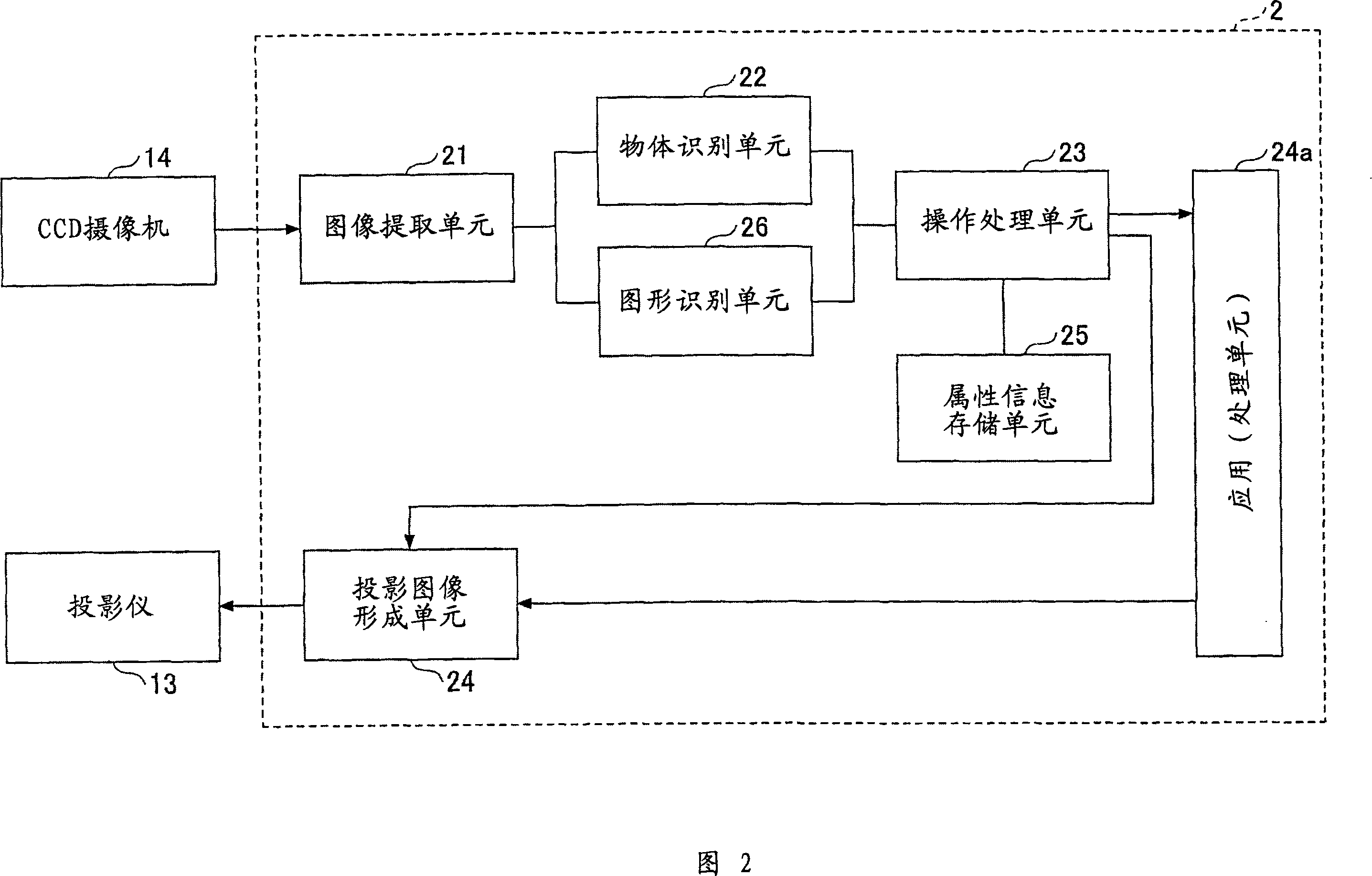
[0388] 59 and 60 are diagrams showing a third embodiment of the image display device according to the present invention. FIG. 59 shows a schematic sectional view of the display unit, and FIG. 60 shows a schematic structural view of the main body unit.
[0389] As shown in FIG. 59, the display unit plane unit 10 of the image display device according to the third embodiment has a plane 11 embedded in its central part; a housing 12 for supporting the plane unit 10; a projector 13 arranged in the housing Inside the body 12, a projector 13 projects an image on a screen 11; a first CCD camera 15 (corresponding to th...
PUM
 Abstract
Description
Claims
Application Information
 - R&D
- Intellectual Property
- Life Sciences
- Materials
- Tech Scout
- Unparalleled Data Quality
- Higher Quality Content
- 60% Fewer Hallucinations
Browse by: Latest US Patents, China's latest patents, Technical Efficacy Thesaurus, Application Domain, Technology Topic, Popular Technical Reports.
© 2025 PatSnap. All rights reserved.Legal|Privacy policy|Modern Slavery Act Transparency Statement|Sitemap|About US| Contact US: help@patsnap.com


