Multi-band or wide-band antenna

一种宽频带、多频带的技术,应用在小型无线通信设备领域,能够解决无法获得带宽等问题,达到天线尺寸减小的效果

Inactive Publication Date: 2008-05-28
YUDONG TECH CO LTD
View PDF8 Cites 23 Cited by
  • Summary
  • Abstract
  • Description
  • Claims
  • Application Information

AI Technical Summary

Problems solved by technology

However, as shown in the patent, due to its non-optimized shape and placement of its main and parasitic top-loaded elements, reasonable bandwidth cannot be obtained, requiring the use of discrete reactive elements in many cases

Method used


Image

  • Multi-band or wide-band antenna
  • Multi-band or wide-band antenna
  • Multi-band or wide-band antenna

Examples


Embodiment Construction

[0027] The preferred embodiment of the present invention is a multi-band antenna. A preferred embodiment of the present invention is described by the general reference numeral 10, as shown in the various drawings herein, and particularly in FIGS. 1a-d.

[0028] Given the convention in the art when discussing antennas that can be used for both transmission and reception, we will number the elements below and discuss their role in transmission below. Those skilled in the art will readily appreciate that although only transmission is discussed, the same elements can still be used in reception.

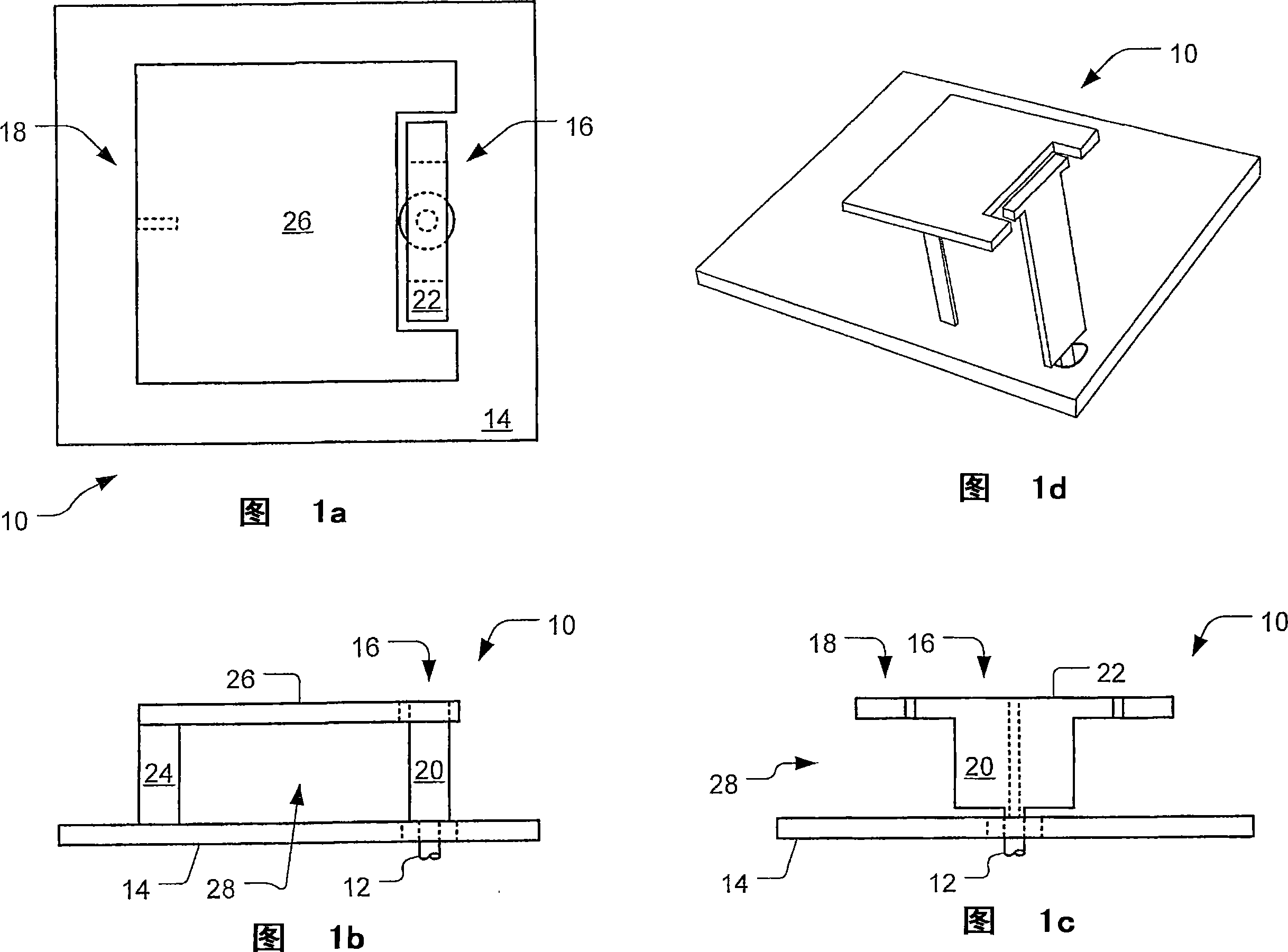
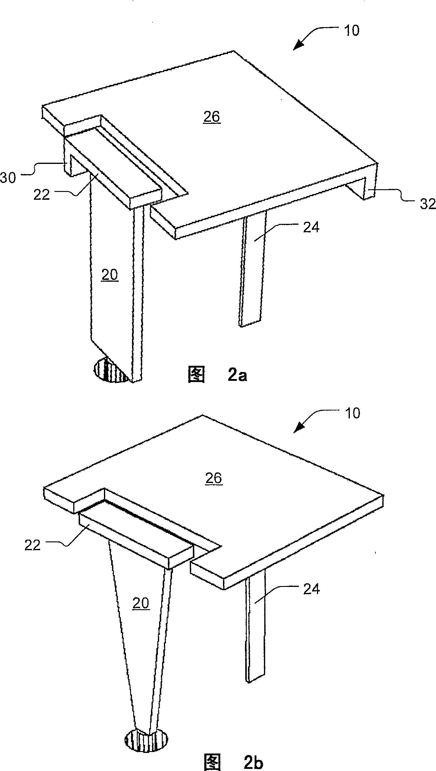
[0029] 1a-d depict a top view, a left side view, a front view and a perspective view, respectively, of an embodiment of an antenna 10 according to the present invention. The antenna 10 here includes a feed point 12 , a ground conductor or surface 14 , a driven radiating portion 16 and a parasitic radiating portion 18 .

[0030] The driven radiating portion 16 includes a feed conductor 2...


PUM


Abstract

A monopole-type antenna(10) for multi- or wide-band use to transmit or receive radio frequency electromagnetic energy. A feed point(12), provides energy into the antenna or receives energy from the antenna. A driven radiating section(12) includes a first top-loading element(22) and a feed conductor(20) that electrically connects the feed point linearly to the first top-loading element(26), yet with the driven radiating section not electrically connected to a grounding surface(14). A parasitic radiating section(18) includes a second top-loading element and a bridge conductor(24) that electrically connects the second top-loading element linearly to the grounding surface When energy is then provided at the feed point and conducted to the driven radiating section, it produces a first resonance mode, coupling at least some of the energy into and exciting the parasitic radiating section to produce a second resonance mode.

Description

technical field [0001] The present invention relates generally to radio wave antennas, and more particularly to radio wave antennas having a lumped reactance at the free end for loading the antenna. It is expected that the present invention will be mainly applied to small wireless communication devices. Background technique [0002] Antennas for wireless communication devices, such as pagers, cellular telephones, and wireless local area network (WLAN) access points, should be small, lightweight, physically compact, and inexpensive to manufacture. Therefore, it is often desirable to even need a flush antenna or an embedded built-in antenna. Furthermore, devices that communicate with wireless services often must operate in different frequency bands due to different geographic frequency band allocation schemes, different wireless providers, different wireless services, or different wireless communication protocols. Such devices accordingly require a single antenna or multiple...

Claims


Application Information

Patent Timeline
Patent Type & Authority Applications(China)
IPC IPC(8): H01Q1/38H01Q5/10
CPCH01Q9/0457H01Q9/0421H01Q9/36H01Q5/50H01Q1/243
Inventor B·塔瓦索尔·霍佐里
Owner YUDONG TECH CO LTD
Why Eureka
Try Eureka