Method for separating pneumatic power transfer transmitting and receiving work terminals and device thereof

A pneumatic transmission and working end technology, applied in the direction of conveyor, transportation and packaging, etc., can solve the problems of unsightly, inconvenient operation, inconvenient to put in the transmission carrier and take out the transmission carrier, etc., and achieve the effect of simple operation and refreshing working environment

Active Publication Date: 2011-07-06
BEIJING RINRONG TECH
View PDF0 Cites 0 Cited by
  • Summary
  • Abstract
  • Description
  • Claims
  • Application Information

AI Technical Summary

Problems solved by technology

[0003] The storage cavity at the working end of the current one-to-one pneumatic pipeline transmission system is integrated with the pipeline, and it is inconvenient to put in and take out the transmission carrier; after being installed on site, it is neither beautiful nor easy to operate

Method used


Image

  • Method for separating pneumatic power transfer transmitting and receiving work terminals and device thereof
  • Method for separating pneumatic power transfer transmitting and receiving work terminals and device thereof
  • Method for separating pneumatic power transfer transmitting and receiving work terminals and device thereof

Examples


example 1

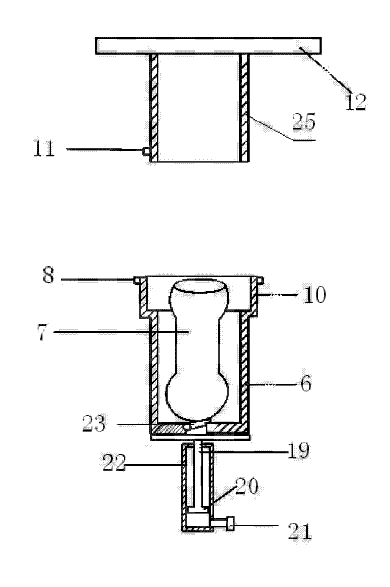
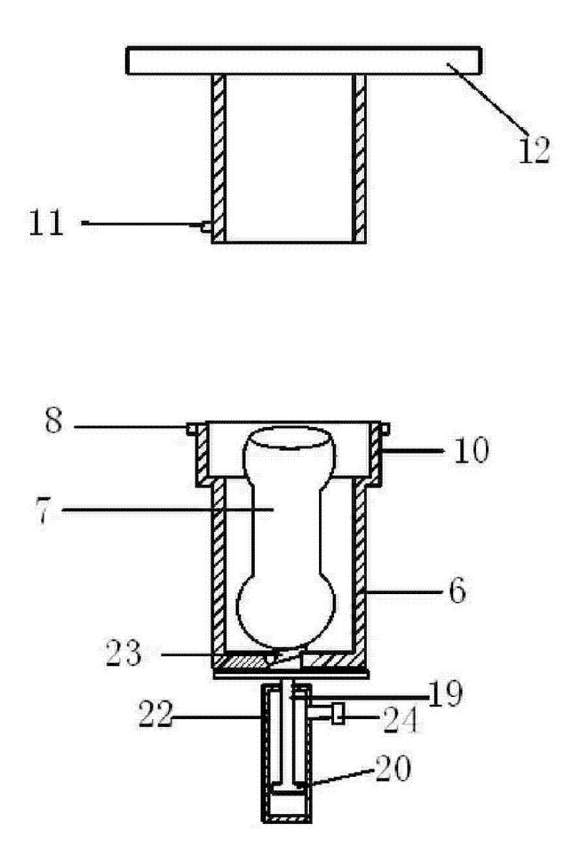
[0054] Such as figure 1 As shown, 23 is an air intake replenishing and exhaust damping mechanism, which is installed on the half part of the pipe section 6 with blocking measures. It is a door connected with the pipe body hinge, and the door can only be opened inwardly. There is a small hole in the place corresponding to the door, and the door can be sealed to replenish the air in time when the transmission carrier is sucked away, and prevent the discharge of air when the transmission carrier falls; 19 is the top bar mechanism, The upper side is fixedly connected to the lower end of the support to connect the piston 20, and the sending and receiving end pipes are installed on the support, and the piston can slide up and down in the cylinder body, and is used to move up and down by the pressure in the cylinder body 22 to drive the sending and receiving end pipes 6 moves up and down, 6 is a pipe section coaxial with the end of the transmission pipeline, and has a cut-off device ...

example 2

[0059] like Figure 4 , 5 As shown, 16 is the pipe section of the sending and receiving working end, which is fixed on the support with a side hinge shaft. After swinging, it is coaxial and has the same diameter as the transmission pipe 6. External force can be added to the working end pipe body or fixed with the working end pipe body. On the connected shaft, after adding force, the two bodies can be anastomosedly connected, and the others are the same as in Example 1.

example 3

[0061] like Image 6 , 7 , Shown in 8, 14 is the horizontal hinge shaft, 16 is the sending and receiving working end pipe section, and the hinge shaft is fixedly connected on the support; other is the same as example 2.


PUM


Abstract

The invention belongs to the field of the transportation of pneumatic tubes. The invention resolves the problems that the existing one to one combination of storage chamber of the working end of the pneumatic tube transportation system and tubes is not only ungraceful but also inconvenient for operation. The working end of the sending and receiving of pneumatic transportation and the tubes are separately disposed, one section of tube the lower end of which has blocking measurement and which has the same diameter with the tubes is utilized as a working end of sending and receiving a transportation bottle and is arranged outside an interface of the tubes. In working time, the sending and receiving end is connected with the tubes via motion under the function of external force. When tasks come, the transportation bottle is placed in the section of tube, and a sensor sends to a main control machine which starts an external force mechanism used as a power portion of the sending and receiving working end. The section of tube disposed at the two ends moves to match and connect with the tubes, an enclosed valve of the receiving end is closed, a negative pressure fan positioned inside the tubes is started, and then the transportation bottle is absorbed to the tubes and moves to the receiving end. When the fan stops, the transportation bottle drops into the tube of the receiving end, then the main control machine orders the receiving end to be opened, thereby the transportation bottle is fetched out from the inner tube of the receiving end, and consequently one operating cycle is accomplished.

Description

[0001] Field [0002] The invention belongs to the field of pneumatic pipeline transmission; in particular, it relates to a separate working end. technical background [0003] The storage cavity at the working end of the current one-to-one pneumatic pipeline transmission system is integrated with the pipeline, and it is inconvenient to put in and take out the transmission carrier; after being installed on site, it is neither beautiful nor easy to operate. [0004] The present invention solves this problem. Contents of the invention [0005] 1. Take a section of pipe with the same diameter as the transmission pipe and a cut-off device at the lower end as the sending and receiving transmission carrier. The working end is set outside the pipe interface; [0006] 2. When working, the sending and receiving end pipes are connected to the transmission pipe through movement under the action of external force, and are coaxial with the transmission pipe port after connection. [000...

Claims


Application Information

Patent Timeline
Patent Type & Authority Patents(China)
IPC IPC(8): B65G51/04B65G51/18B65G51/26B65G51/36
Inventor 陆洪瑞
Owner BEIJING RINRONG TECH
Why Eureka
Try Eureka