Supercharge Your Innovation With Domain-Expert AI Agents!

3d movement input device

A technology of three-dimensional movement and input device, which is applied in the direction of instrument, data processing input/output process, electrical digital data processing, etc., to achieve the effect of easy grip

Active Publication Date: 2008-06-11
SHIMA SEIKI MFG LTD
View PDF1 Cites 0 Cited by
  • Summary
  • Abstract
  • Description
  • Claims
  • Application Information

AI Technical Summary

Problems solved by technology

However, it is difficult to input motion while considering 6 axes with respect to the ring

Method used


Image

  • 3d movement input device
  • 3d movement input device
  • 3d movement input device

Examples


Embodiment Construction

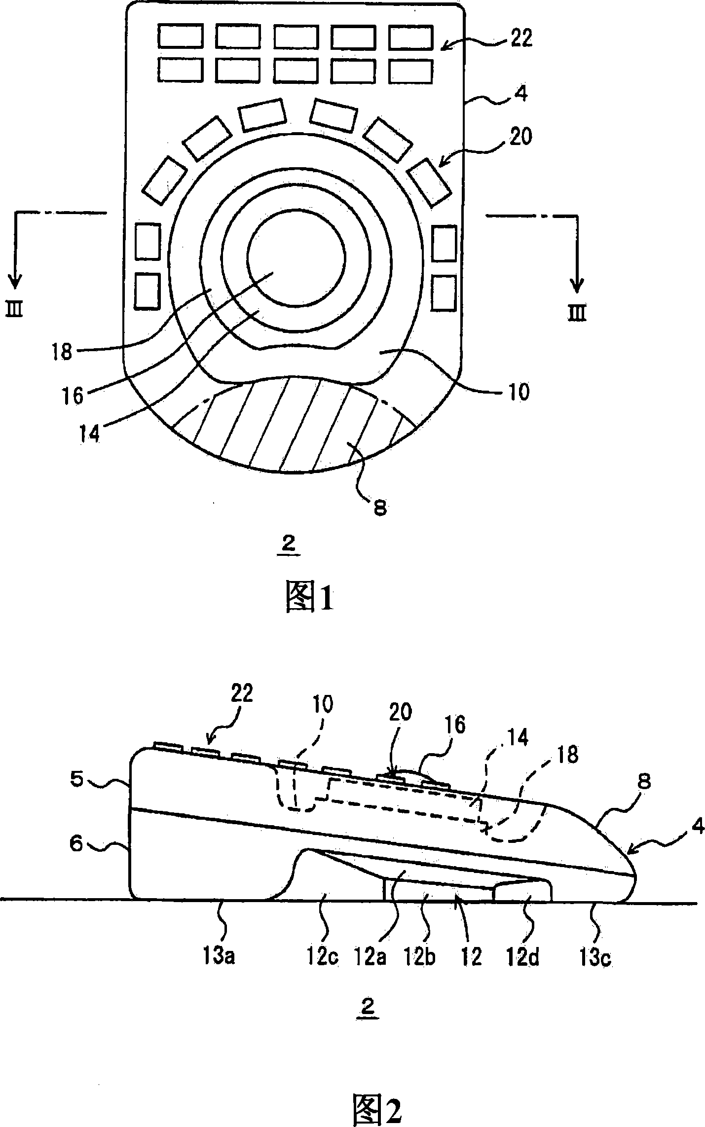
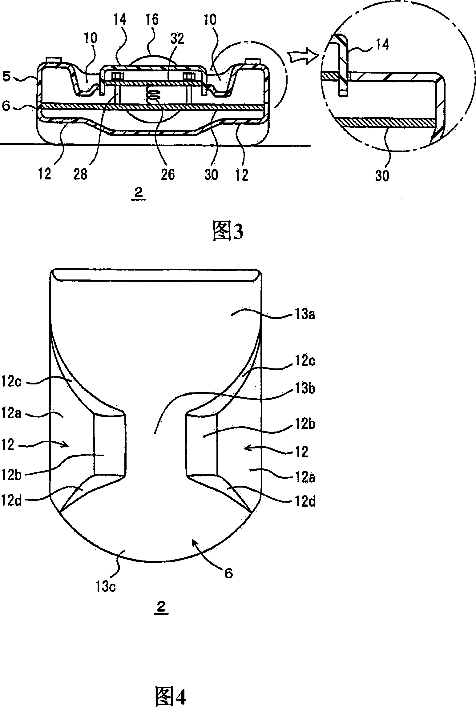
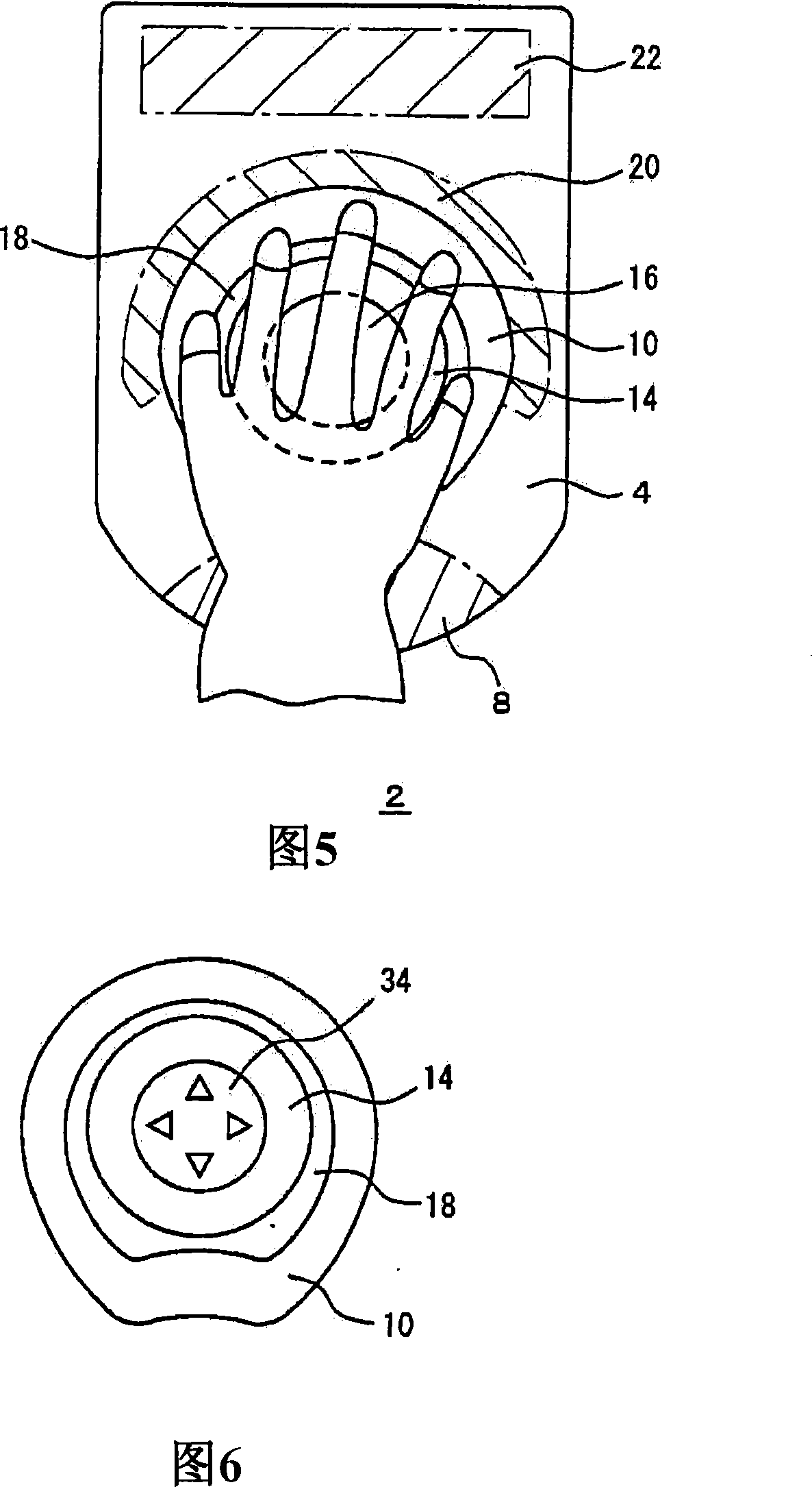
[0039] 1 to 17 show the motion commander 2 of the embodiment and its modification. Motion commander 2 is used for the input of 3D movement, and 4 is housing, is made up of upper housing 5 and lower housing 6, below the lower side of Fig. 1 is referred to as near side, and upper side is referred to as front end, and left and right sides of Fig. 1 called left and right. The motion commander 2 is inclined so as to increase in height from the front side to the front end, and has an inclined surface rising from the front edge on the front side, which is used as a hand rest 8 . In contact with the hand support 8, there is an annular groove 10 in the center of the upper surface of the housing, and there are depressions 12 on both sides of the lower housing 6. 12a-12d are the inclined surfaces of the depressions 12. The bottom surface of the lower housing 6 is, for example, formed by The flat surfaces 13a to 13c shown in FIG. 4 are configured, and the flat surface 13b may not be prov...


PUM


Abstract

The upper surface of the casing (4) of the movement commander (2) is arranged with an annular groove (10), the input used ring (14) and tracing ball (16) which move with 3D area arranged at the inner side. The 2D movement is inputted by the tracing ball (16) and the four-axis 3D movement except for the 2D movement is eliminated by the operation input of the ring (14). Therefore the 3D movement can be easily inputted.

Description

technical field [0001] The invention relates to a structure of a three-dimensional motion input device. Background technique [0002] Patent Document 1 discloses that a ring is provided with a slit, and the direction of the slit is detected by detecting light passing through the slit. And when the ring can move three-dimensionally relative to the base, the six-axis motion of the ring can be detected through six slits, and the three-dimensional motion can be input. However, it is difficult to input motion while considering six axes with respect to the ring. Therefore, the inventors of the present invention worked hard to develop a three-dimensional motion input device that is easy to input 6-axis motion and is ergonomically excellent, and arrived at the present invention. [0003] Patent Document 1 Japanese Patent Publication Hei 4-57202 Contents of the invention [0004] The object of the present invention is to facilitate the input of three-dimensional motion. [0005...

Claims


Application Information

Patent Timeline
IPC IPC(8): G06F3/033G01D5/26G01D5/12G06F3/0354G06F3/0362
Inventor 奥野纮规神德泰孝
Owner SHIMA SEIKI MFG LTD
Features
  • R&D
  • Intellectual Property
  • Life Sciences
  • Materials
  • Tech Scout
  • Unparalleled Data Quality
  • Higher Quality Content
  • 60% Fewer Hallucinations
Learn More