Caching management method and caching management system

A cache management and cache system technology, applied in transmission systems, digital transmission systems, electrical components, etc., can solve problems such as cache system performance degradation, cache leaks, and cache addresses that cannot be released normally, so as to avoid cache capacity reduction and reduce Effects of cache leaks

Inactive Publication Date: 2008-06-11
NEW H3C TECH CO LTD
View PDF0 Cites 14 Cited by
  • Summary
  • Abstract
  • Description
  • Claims
  • Application Information

AI Technical Summary

Problems solved by technology

[0004] In practical applications, the address release unit 140 may fail to receive the cached message related information sent by the address requesting unit 110 for some reason, and the cached message will always be stored in the cache unit 130. The occupied cache address cannot be released normally
Then the cache address occ

Method used


Image

  • Caching management method and caching management system
  • Caching management method and caching management system
  • Caching management method and caching management system

Examples


Embodiment Construction

[0035] The present invention will be described in detail below with reference to the accompanying drawings and examples.

[0036] The present invention is a cache management scheme, the basic idea of ​​which is: each time the timing reaches the cycle timing time, the cache address in the applied state is released to ensure that the cache addresses that have been applied for can be recycled, thereby reducing cache leakage.

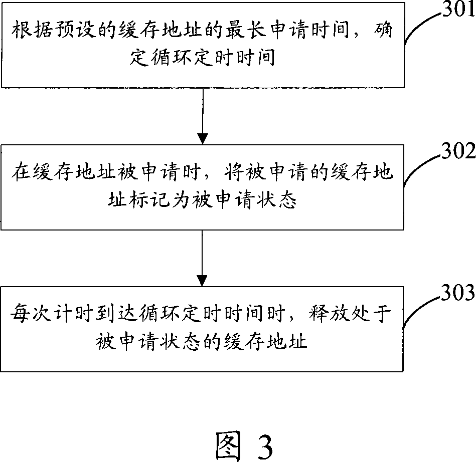
[0037] Figure 3 shows an exemplary flowchart of a cache management method based on the above basic idea, as shown in Figure 3, the method includes the following steps:

[0038] Step 301: Determine the cycle timing time according to the preset longest application time of the cache address.

[0039] Step 302: When a cache address is applied for, mark the applied cache address as being applied for.

[0040] Step 303: Release the cache address in the requested state each time the timing reaches the cycle timing time.

[0041] Here, the longest application tim...


PUM


Abstract

The invention discloses a buffer management method which comprises the following steps: when a buffer address is applied, the applied buffer address is marked as applied state; when cycle timing time which is determined according to maximum application time of the buffer address is reached each time by time keeping, the buffer address in the applied state is released. The invention also provides a buffer management system. By utilization of the invention, all applied buffer addresses can be initiatively released in definite time, and all the applied buffer addresses are guaranteed to be able to be withdrawn, thereby buffer leakage is reduced.

Description

technical field [0001] The invention relates to cache technology, in particular to a cache management method and a cache management system. Background technique [0002] FIG. 1 is a schematic structural diagram of an existing caching system. As shown in FIG. 1 , the system includes an address request unit 110 , a cache management unit 120 , a cache unit 130 and an address release unit 140 . Wherein, after the address request unit 110 receives the message to be cached, it proposes an address application request to the cache management unit 120, and after applying for the cache address, saves the message to be cached on the cache address in the cache unit 130, and sends the cached message to the address release unit 130. 140 sends the cached message-related information including the cached address; the address release unit 140 reads the corresponding message from the cache unit 130 according to the cached address in the cached message-related information and outputs it, and s...

Claims


Application Information

Patent Timeline
IPC IPC(8): H04L12/56H04L49/9015
Inventor 王彬
Owner NEW H3C TECH CO LTD
Why Eureka
Try Eureka