
Image processing apparatus and method, program and readable memory medium for computer

An image processing equipment and image technology, applied in image data processing, image data processing, computer parts and other directions, can solve the problems of adding data embedded in paper fingerprint areas, difficult to find auxiliary data, forgery, etc., to prevent security. the effect of interference

Inactive Publication Date: 2008-06-11
CANON KK
View PDF5 Cites 7 Cited by
  • Summary
  • Abstract
  • Description
  • Claims
  • Application Information

AI Technical Summary

Problems solved by technology

[0006] However, the technique disclosed in Japanese Patent Application Laid-Open No. 2004-214831 embeds auxiliary data for tracking and investigating counterfeit copying into an image portion of a paper form, making it difficult to find the auxiliary data
This technique has the effect of making it difficult to falsify auxiliary data, but has the following problem: if the auxiliary data embedded in the image part is hidden due to cutting and pasting, forgery can be performed
Therefore, in the case where a desired messy part is not generated or otherwise, there arises a problem that the originality can no longer be guaranteed
[0008] In addition, the technique disclosed in Japanese Patent Application Laid-Open No. 2004-112644 is a technique for determining a reading area using a mark added to a used paper form as a reference, but this technique does not consider whether the area is a paper fingerprint area. suitable area
Therefore, there is a problem that this technique judges an area that cannot be read correctly, such as a solid black area, as a read area.
[0009] In addition, the technique disclosed in Japanese Patent Application Laid-Open No. 2001-127983 is a technique of obtaining the average concentration of a predetermined area and determining the area in which the added data is embedded, but this technique does not consider the collation rate after changing the area
Therefore, in the case where an area with a low contrast ratio such as a completely black area extends near a predetermined area, there is a problem that even when the area is changed according to the average density, additional data may be embedded in the area where the paper fingerprint cannot be read correctly. in the area

Method used


Image

  • Image processing apparatus and method, program and readable memory medium for computer
  • Image processing apparatus and method, program and readable memory medium for computer
  • Image processing apparatus and method, program and readable memory medium for computer

Examples


no. 1 example

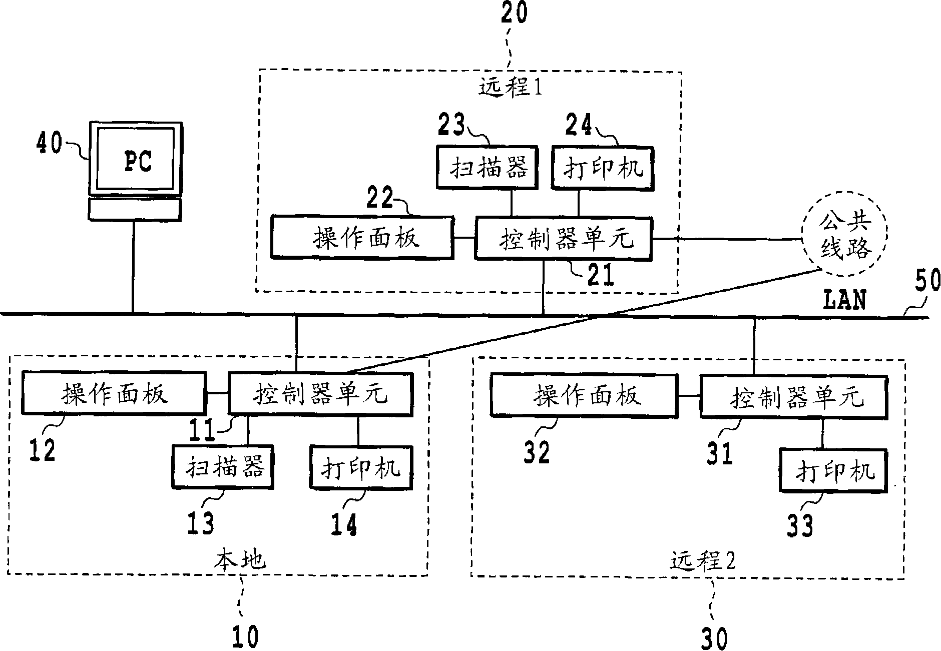
[0060] printing system ( figure 1 )

[0061] A first embodiment will be described in detail with reference to the drawings. figure 1 is a block diagram showing the configuration of a printing system according to an embodiment of the present invention. In this system, a host computer 40 and three image forming apparatuses ( 10 , 20 and 30 ) are connected to a LAN 50 . However, in the printing system in this embodiment, the number of these members connected is not limited thereto. Furthermore, although LAN is employed as the connection method in this embodiment, this embodiment is not limited thereto. For example, arbitrary networks such as WAN (public line), serial transmission methods such as USB, and parallel transmission systems such as Centronics and SCSI can be used.

[0062] The host computer (hereinafter referred to as PC) 40 has the function of a personal computer. The PC 40 can send / receive files and send / receive e-mails via the LAN 50 or WAN using the FTP or SM...

no. 2 example

[0186] An embodiment will be described in the case where a scanner is installed in the main body of the image forming apparatus.

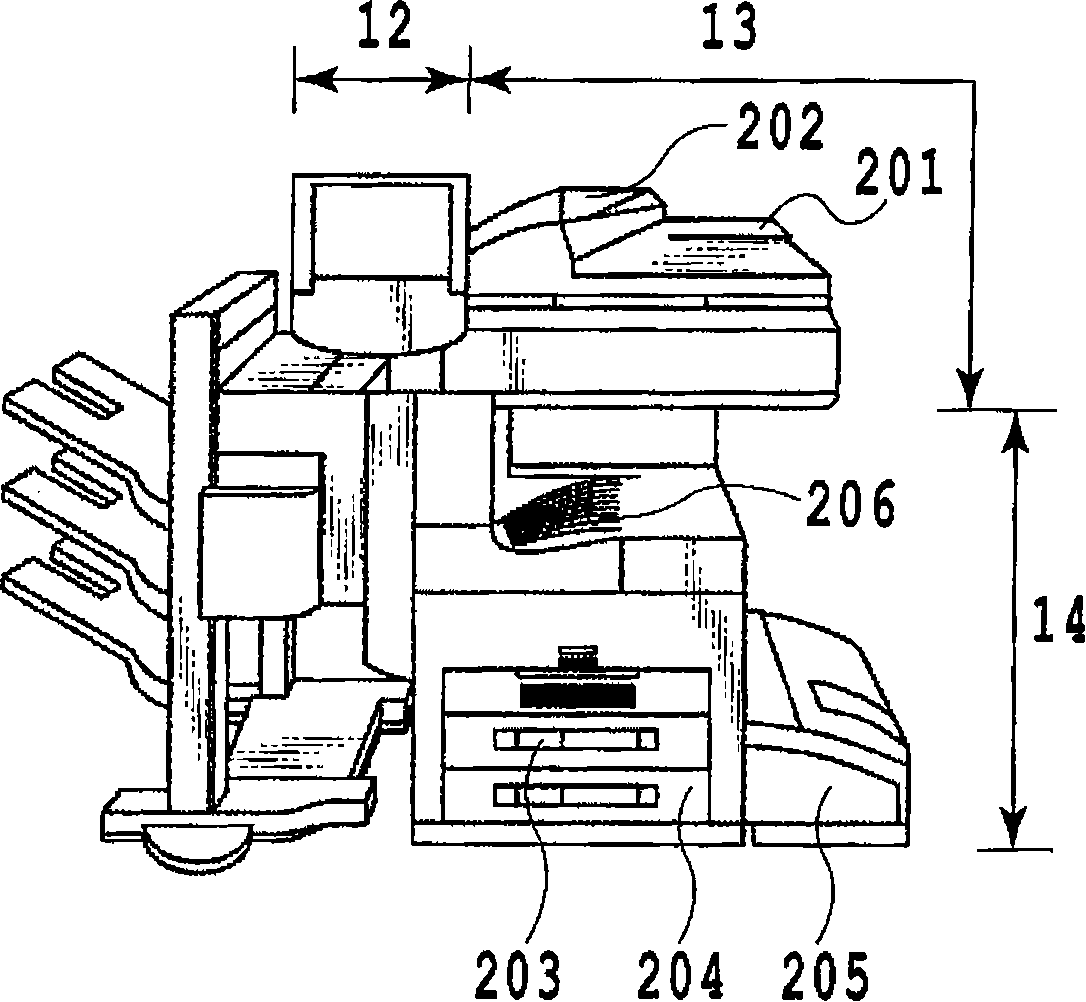
[0187] Figure 26 The structure of the main body of the image forming apparatus is shown. At the time of printing, the image forming apparatus performs a series of processes of taking out a paper form from a sheet stocker, placing a toner image on the paper form in the photosensitive drum, and fixing the image on the paper form in the fixing section. In the second embodiment, the image forming apparatus is configured to form an image by installing a scanner in the post-processing of the fixing section and read the paper fingerprint by the scanner, read the image, and perform a series of paper fingerprint information registration processing. deal with.

[0188] Figure 27 The internal structure of the main body of the image forming apparatus in this embodiment is shown. Reference numeral 2701 is a scanner section installed inside the main body. ...

no. 3 example

[0194] In the first embodiment, a form was described in which, in order to designate an area including a few or several image areas (image-containing area) as a paper fingerprint registration area in paper fingerprint information acquisition processing, the number of image areas including a certain threshold value The area is determined as the paper fingerprint area. Specifically, such as Figure 11 As shown in the flow chart of , an edge determination is performed on an area of ​​a predetermined size read by the scanner unit 13 to determine whether or not an image area is included. In this embodiment as another embodiment, the embodiment of determining the area suitable for the paper fingerprint area, more specifically, the area with the highest contrast ratio of the paper fingerprint as the paper fingerprint area is described in more detail. Here, since the controls and units are the same as those of the first embodiment except for the area for determining the highest contr...


PUM


Abstract

The invention provides an image processing apparatus and a method therefor capable of registering a paper fingerprint at a position that considers a matching accuracy and security. The image forming apparatus executes: a paper fingerprint acquisition step of reading a paper fingerprint (S1101-S1104); a paper fingerprint registration determination step of determining whether paper fingerprint information acquired in the paper fingerprint information acquisition step is suitable as a paper fingerprint for paper (51105-51107) ; and a paper fingerprint registration step of registering a paper fingerprint detected in the paper fingerprint registration determination step as a paper fingerprint for the paper (s803).

Description

technical field [0001] The present invention relates to an image processing device and an image processing method, and more particularly, to an image processing device capable of processing information of paper fibers, so-called paper fingerprint information, an image processing method, a program, and a recording medium thereof. Background technique [0002] Conventionally, there is a technique of embedding auxiliary data such as a model number in image data in order to trace and investigate forged copies of documents in digital multifunctional machines. In addition, in the process of embedding auxiliary data, there is a technique of embedding auxiliary data in a position that is difficult to be found by a third party when embedding processing is performed in order to prevent a third party from easily finding and decoding the auxiliary data from a printed image . For example, Japanese Patent Application Laid-Open No. 2004-214831 discloses this technique. [0003] In additi...

Claims


Application Information

Patent Timeline
Patent Type & Authority Applications(China)
IPC IPC(8): H04N1/00G06T1/00G03G21/00G06V20/80G06T7/00H04L9/32H04N1/40
CPCH04N1/0048H04N1/32101H04N2201/3236G07D7/2033H04N2201/3235G06K9/00H04N1/00411G06K9/00577G06V20/80G06V30/41
Inventor 九里史朗小桥和文
Owner CANON KK
Learn More