Jig lifting apparatus

A technology of lifting devices and fixtures, which is applied to assembly machines, manufacturing tools, workbenches, etc., and can solve problems such as difficult positioning

Active Publication Date: 2008-06-18
AISIN AW CO LTD
View PDF1 Cites 5 Cited by
  • Summary
  • Abstract
  • Description
  • Claims
  • Application Information

AI Technical Summary

Problems solved by technology

[0005] However, when assembled manually by the operator, the parts must be correctly positioned relative to the casing of the automatic transmission, but since the inside of the casing is deep, it is difficult for the operator to do so visually from the outside.

Method used


Image

  • Jig lifting apparatus
  • Jig lifting apparatus
  • Jig lifting apparatus

Examples


Embodiment Construction

[0023] The best mode for carrying out the present invention will be described below using examples.

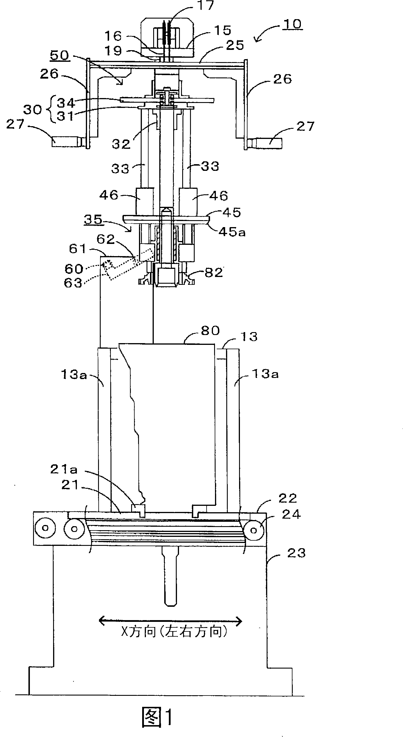
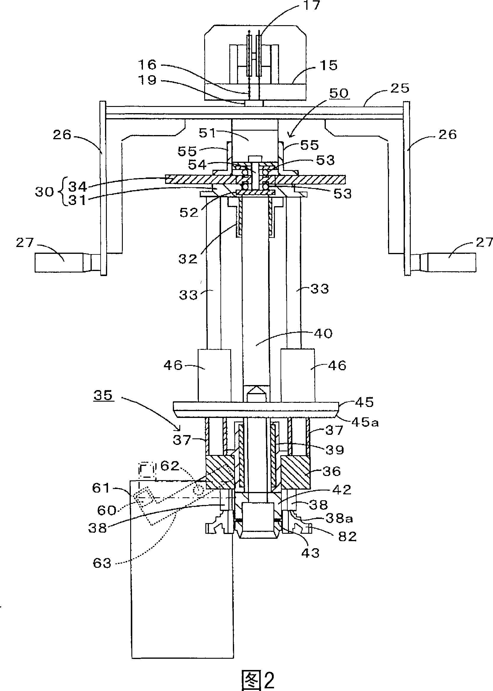
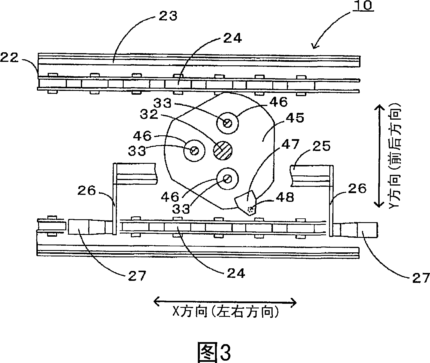
[0024] Fig. 1 is a front view of the clamp elevating device 10 of the present embodiment, Fig. 2 is an enlarged front view (partial sectional view) of the clamp 35, Fig. 3 is a top view (partial sectional view) of the clamp elevating device 10, Fig. 4 is a clamp elevating device 10 side view.

[0025] The jig lifting device 10 of the present embodiment has: a device stand 12; a pallet (pallet) 21 as a housing support platform, which is arranged below the device stand 12; a sliding seat 25 as a moving body, which is installed on the device stand 12, and can move up and down relative to the supporting plate 21; the horizontal plate 30, which is installed on the slide seat 25; the clamp 35, which is fixed on the lower ends of the three rods 33 extending downward from the horizontal plate 30; the base part 45 , which is installed on these rods 33 in a manner that can move up and ...


PUM


Abstract

The invention provides a clamp lifting device which can position a part or an examined component easily when assembling or examining components inside a shell with a clamp through the manual operation of an operator. The clamp lifting device is characterized in that the components are assembled inside the AT shell through a clamp positioned at the lower end of a rod extending downwards from a horizontal board. The rod is provided with a base seat component which can move upwards and downwards. Besides, the horizontal board, the clamp and the base seat component move downwards together when a downward force is stressed to a slide seat by an operator; and the horizontal board and the clamp move downwards when the base seat component is arranged at the reference position of the AT shell. Therefore, the base-seat component micro-moves together with the horizontal board along the horizontal direction through a float mechanism, thereby correcting the departure easily even if any departure appears in the relative position of the AT shell and the clamp.

Description

technical field [0001] The invention relates to a clamp lifting device. Background technique [0002] Automatic transmissions mounted on automobiles have been known for a long time. For example, in Patent Document 1, an automatic transmission provided with a torque converter and a multi-stage transmission mechanism having a plurality of planetary gears is disclosed. In this automatic transmission, a one-way clutch that connects or disconnects gears constituting planetary gears and an input shaft, restricts rotation of each gear, and the like is provided in a housing. [0003] Patent Document 1: JP Unexamined Patent Application Publication No. 2002-161951. [0004] However, when assembling such an automatic transmission, there is a method of automatically assembling by moving a jig from an upper position to a lower position with a servo motor. On the other hand, it is desirable to assemble the automatic transmission manually by an operator without using a servo motor. [...

Claims


Application Information

Patent Timeline
Patent Type & Authority Applications(China)
IPC IPC(8): B23P21/00B25H1/10
Inventor 谷口孝男新土史夫近藤展充桥本邦之富田武
Owner AISIN AW CO LTD
Why Eureka
Try Eureka