Eureka AIR delivers breakthrough ideas for toughest innovation challenges, trusted by R&D personnel around the world.

Display device, terminal device, display panel, and optical member

A display device and display panel technology, applied in optics, nonlinear optics, electrical components, etc., can solve problems such as reducing image quality, and achieve the effect of improving image quality and reducing impact

Inactive Publication Date: 2008-06-18
NEC LCD TECH CORP
View PDF3 Cites 25 Cited by
  • Summary
  • Abstract
  • Description
  • Claims
  • Application Information

AI Technical Summary

Problems solved by technology

[0012] As a result of intensive research on display devices having lenticular lenses, parallax barriers, or other optical components, the inventors have found that in these display devices, patterns of adjacent pixels or border regions of other intervals that are not useful for display are observed as Parallel lines in the alignment of lenses or slits, and problems that degrade image quality

Method used


Image

  • Display device, terminal device, display panel, and optical member
  • Display device, terminal device, display panel, and optical member
  • Display device, terminal device, display panel, and optical member

Examples


Embodiment Construction

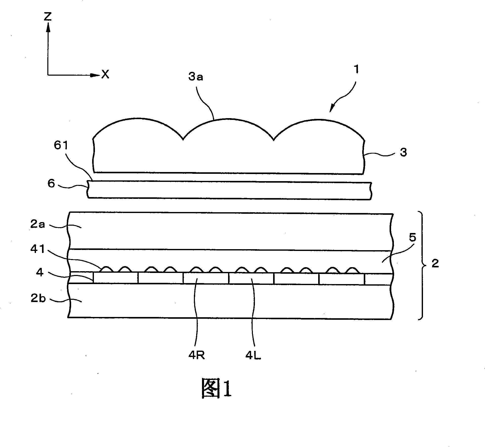
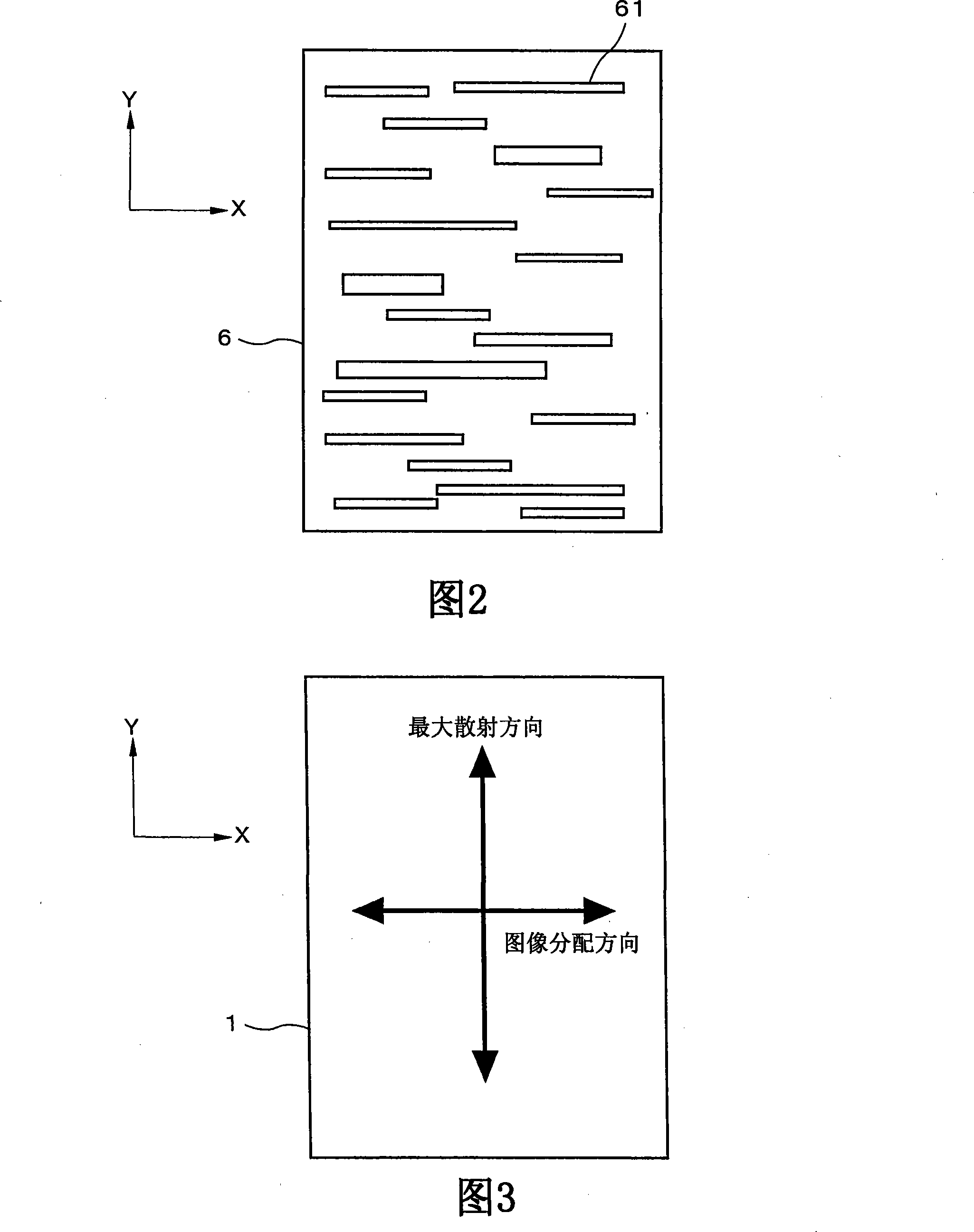
[0073] The display device of the present invention can be constructed as follows. That is, the display device of the present invention includes: a display panel in which a plurality of display units including at least pixels for displaying an image for a first viewpoint and pixels for displaying an image for a second viewpoint are arranged in a matrix; an image distributing section for distributing light emitted from the pixels to different directions along a first direction along which pixels for displaying an image for a first viewpoint and for displaying an image for a first viewpoint are arranged in the display unit a pixel for an image of the second viewpoint; and an anisotropic scattering section for scattering incident light or outgoing light with respect to the display panel so that scattering in a second direction perpendicular to the first direction is different from the first direction Scattering in .

[0074] In the present invention, it is possible to prevent deg...


PUM


Abstract

The present invention relates to a dispaly device, a terminal unit, a display panel and optical member. A reflective liquid crystal display panel is a display panel for three-dimensional display in which pixel pairs as display elements composed of one left-eye pixel L and one right-eye pixel R each are provided in a matrix. The lenticular lens is an optical member for image separation that is provided to separate the light from the left and right pixels, and numerous lenticular lenses form a lens array that is arranged in one dimension. An anisotropic scattering sheet as an anisotropic scattering element is provided between the lenticular lens and the reflective liquid crystal display panel. According to this configuration, a reduction in the quality of the reflective display can be minimized, and improved image quality can be achieved without changing the concavo-convex structure of the reflecting panel and the lens shape of the lenticular lens in display device that is capable of displaying different images to a plurality of viewpoints.

Description

technical field [0001] The present invention relates to a display device capable of displaying images to each of a plurality of viewpoints, to a terminal device, and more particularly, to a display device capable of reducing deterioration of display quality caused by a structure of the display device, to a terminal device, and to a terminal device A display panel and an optical member that can be suitably used in display devices and terminal devices. Background technique [0002] Due to recent technological developments, display panels are configured and used in monitors, television receivers and other large terminal equipment; notebook personal computers, automatic teller machines, vending machines and other medium-sized terminal equipment; and personal TVs, PDAs (personal digital assistants: personal information terminals), mobile phones, mobile game devices and other small terminal devices in various locations. Especially, display devices using liquid crystals are deploy...

Claims


Application Information

Patent Timeline
IPC IPC(8): G02F1/1335H04N13/00
Inventor 上原伸一
Owner NEC LCD TECH CORP
Why Eureka
Eureka Blog
Learn More