
Touch pad and position sensing method for the same

A touch panel and touch position technology, applied in the input/output process of data processing, instruments, electrical digital data processing, etc., can solve the problems of general products and methods without structure and method, inconvenience, etc., and achieve the position detection method Improvement, simple wiring, low cost effect

Inactive Publication Date: 2008-06-18
ELAN MICROELECTRONICS CORPORATION
View PDF0 Cites 17 Cited by
  • Summary
  • Abstract
  • Description
  • Claims
  • Application Information

AI Technical Summary

Problems solved by technology

[0006] It can be seen that the above-mentioned existing touch panel and its position detection method obviously still have inconvenience and defects in product structure, detection method and use, and need to be further improved urgently.
In order to solve the above-mentioned problems, the relevant manufacturers have tried their best to find a solution, but no suitable design has been developed for a long time, and there is no suitable structure and method for general products and methods to solve the above-mentioned problems. This is indeed one of the current important research and development topics, and it has also become a goal that the industry needs to improve.

Method used


Image

  • Touch pad and position sensing method for the same
  • Touch pad and position sensing method for the same
  • Touch pad and position sensing method for the same

Examples


Embodiment Construction

[0042] In order to further explain the technical means and effects of the present invention to achieve the intended purpose of the invention, the following in conjunction with the accompanying drawings and preferred embodiments, the touch panel proposed according to the present invention and its position detection method for the touch panel Its specific implementation, structure, method, feature and effect thereof are described in detail as follows.

[0043] The aforementioned and other technical contents, features and effects of the present invention will be clearly presented in the following detailed description of preferred embodiments with reference to the drawings. Through the description of the specific implementation mode, when the technical means and effects adopted by the present invention to achieve the predetermined purpose can be obtained a more in-depth and specific understanding, but the accompanying drawings are only for reference and description, and are not use...


PUM


Abstract

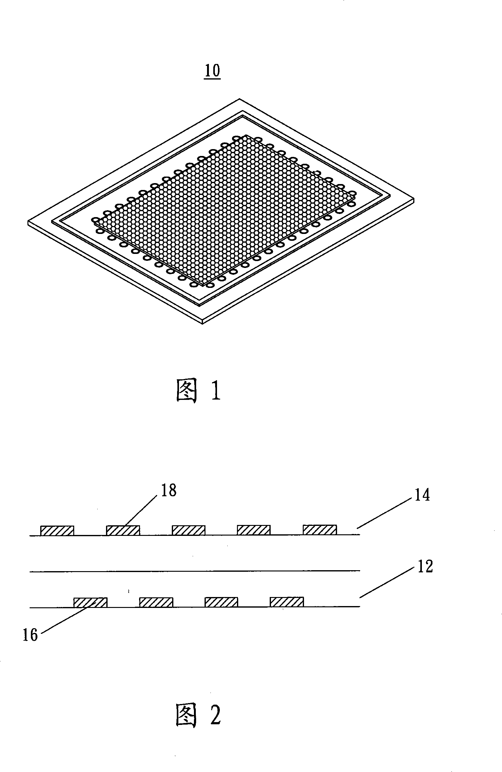
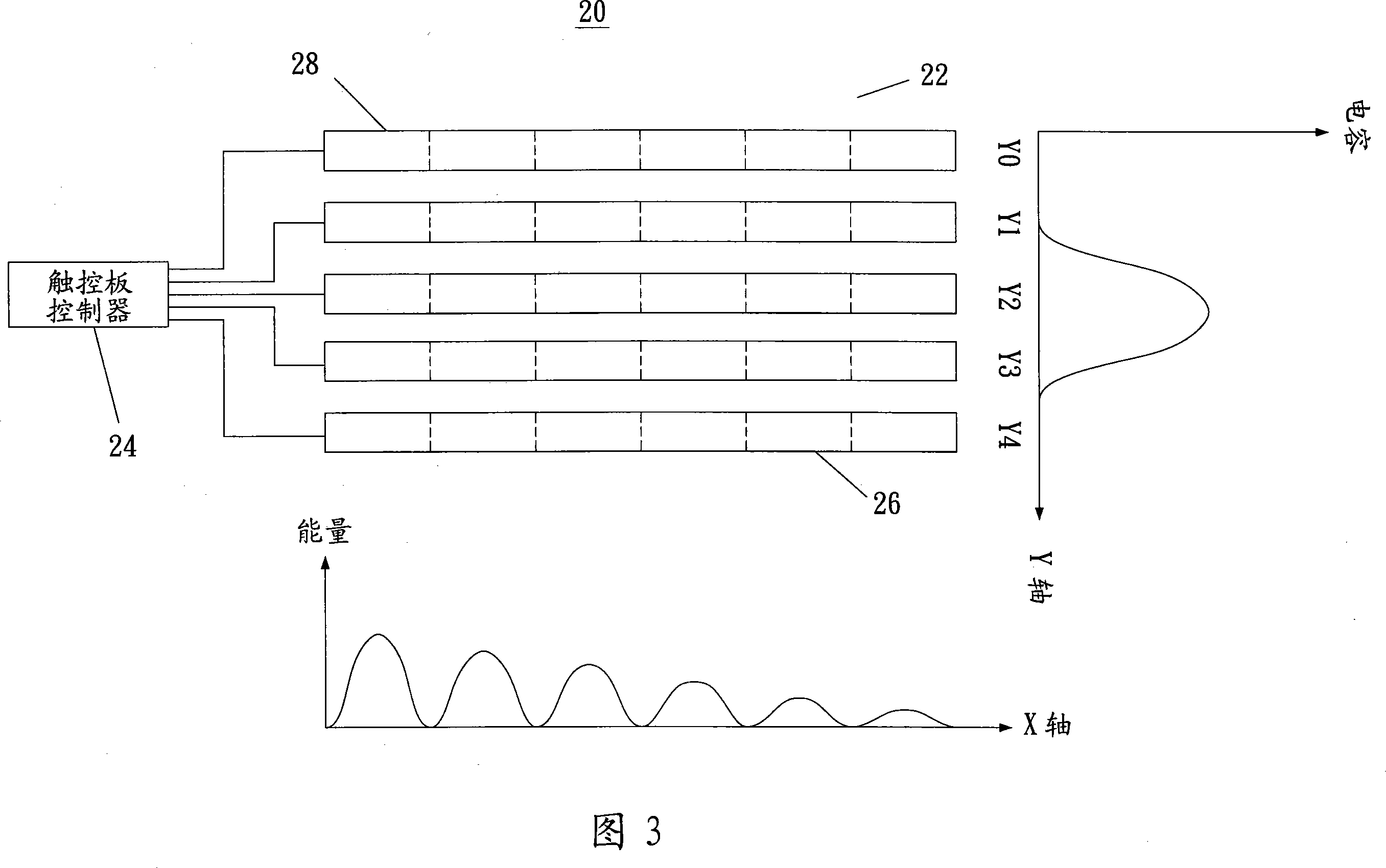
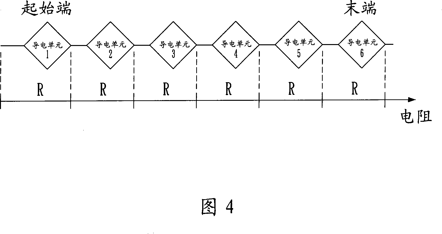
The invention relates to a touch panel and a position detection method for the touch panel. The touch panel includes a substrate and a single-layer circuit layout formed on the substrate. The single-layer circuit layout includes a plurality of conductive lines, and each conductive line has a resistance value that gradually changes with the distance from one end thereof. The position detection method is used to detect a contact position of a contact object on a touch panel equipped with multiple conductive lines, and the parts of the conductive lines arranged at the position detection positions are arranged at intervals in a first dimension direction, along a first dimension. The two-dimensional directions extend in parallel, and the unit resistance value of the conductive lines extending in parallel along the second dimensional direction changes with the distance from one end of the conductive lines. The method includes: calculating the resistance and capacitance of each conductive line The sum of the products, and the second dimension direction coordinate value of the contact position is judged according to the calculated sum. The present invention has the advantage of lower cost through simple wiring, and can use one-dimensional wiring detection lines to achieve two-dimensional position positioning, which is very practical.

Description

technical field [0001] The present invention relates to a structure of a touch panel and a detection method thereof, in particular to a touch panel with a single-layer wiring, which can use a one-dimensional wiring detection line to achieve two-dimensional position positioning and its application to the touch panel. location detection method. Background technique [0002] Currently, many manufacturers use capacitive touch sensing devices. The main advantage of capacitive touch sensing technology is that it is very sensitive to fingers, and a very light touch on the touchpad will be accurately sensed. This feature makes capacitive touch sensors ideal as pointing devices for computers. [0003] So far, the objects that can be used on capacitive sensors are limited to conductive objects (such as human fingers) that have a large contact area with the touchpad and generate a capacitance large enough to be detected. Small or non-conductive objects are difficult to detect becaus...

Claims


Application Information

Patent Timeline
Patent Type & Authority Applications(China)
IPC IPC(8): G06F3/041
Inventor 叶仪晧李文凯
Owner ELAN MICROELECTRONICS CORPORATION
Learn More