Roller hemming device and roller hemming method

一种卷边装置、辊式的技术,应用在辊式卷边技术的改良领域,能够解决褶皱聚集、起波纹成品形状、不能适用白合金车身等问题,达到没有褶皱聚集、良好卷边加工的效果

Inactive Publication Date: 2008-06-18
HONDA MOTOR CO LTD
View PDF2 Cites 13 Cited by
  • Summary
  • Abstract
  • Description
  • Claims
  • Application Information

AI Technical Summary

Problems solved by technology

[0013] If roll hemming is performed with the gap 125 left, so-called wrinkle accumulation and waviness will occur, resulting in poor shape of the finished product
Since the gap 125 cannot be allowed, the clamping force will be strengthened to eliminate the gap 125, which will cause extrusion damage on the holding arm 121 or deform the holding arm 121.
[0014] For the above reasons, the roll hemming using the existing hemming die 101 cannot be applied to rigid parts such as white metal car bodies.

Method used


Image

  • Roller hemming device and roller hemming method
  • Roller hemming device and roller hemming method
  • Roller hemming device and roller hemming method

Examples


Embodiment Construction

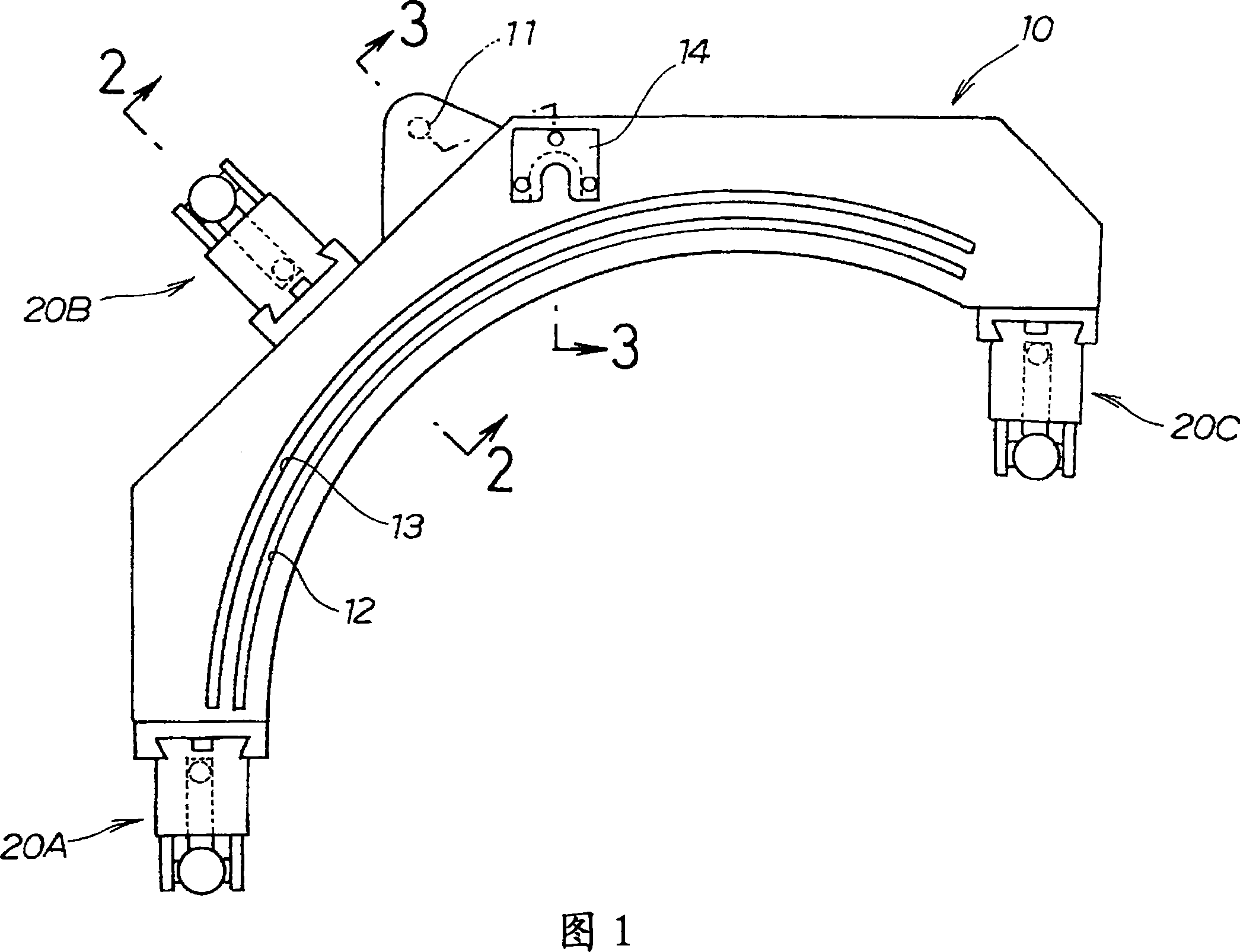
[0061] Hereinafter, typical embodiments of the present invention will be described based on the drawings. Also, the orientation of the drawings matches the orientation of the symbols. Fig. 1 is the front view of the supporting mold of the roller hemming device of typical embodiment of the present invention, and the roller hemming device is composed of the roller mechanism (symbol 40 of Fig. 4,5) installed on the mechanical arm and detachable ground The supporting mold 10 attached to this attachment constitutes.

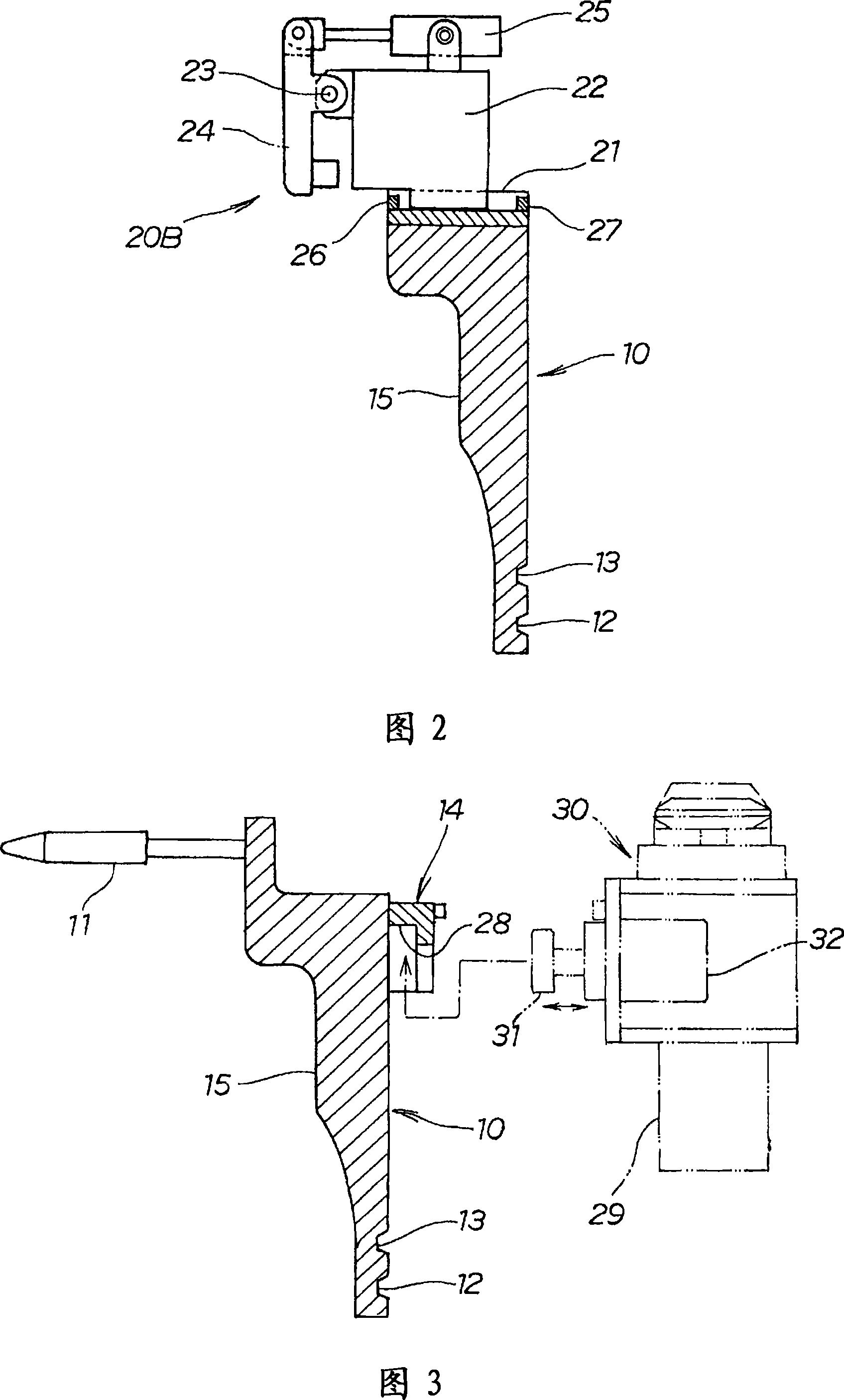
[0062] In this die 10, there are bearing surfaces (illustrated with FIG. 2.) and positioning pins 11 on the surface on the rear side of the figure, and a first guide groove 12, a second guide groove 13, and a first guide groove 12 on the surface near the figure. The clamping portion 14 capable of clamping from the outside has clamping mechanisms 20A, 20B, and 20C at the lower left end, upper edge, and right end, respectively.

[0063] Fig. 2 is the 2-2 line sectiona...


PUM


Abstract

A roller (48) starts to bend a standing flange (65) in the initial state of a roller hemming processing. A first plate material (63) is fitted to a receiving face (15) by the strong holding action of the roller (48) and an auxiliary roller (51) at a contact point (70) between the roller (48) and the standing flange (65). On the other hand, the receiving face (15) tends to be separated from the first plate material (63) by the reaction thereof at those portions other than the contact point (70). Since slider blocks (22) and (22) are movable along rails (21) and (21) on a receiving mold (10), the receiving mold (10) is rotated clockwise about the contact point (70) (as shown in the figure). Since the receiving mold (10) is rotated about the contact point (70), the adhesiveness of the first plate material to the receiving face at the contact point (70) can be assured. As a result, the hemming processing free from wrinkles, waving, and deformation to provide excellent shape can be achieved.

Description

technical field [0001] The present invention relates to the improvement of roll hemming technology. Background technique [0002] The processing technique of overlapping two sheet materials and bending the edge of one sheet onto the edge of the other sheet to connect the edges of the two sheet materials has been widely practiced, and this technique is called hemming. [0003] Among the hemming techniques, the pressure hemming method using a die is well known, but there is also a roll hemming method using another method (for example, refer to Japanese Patent Publication No. 7-16731 ​​(FIGS. 1 and 3).). [0004] Japanese Patent Application Publication No. 7-16731 ​​will be described based on the drawings described later. Fig. 16(a) and Fig. 16(b) are diagrams explaining the basic principle of the prior art. In FIG. 16( a ), a workpiece 102 is placed on a crimping die 101 , and the edges of the workpiece 102 are pressed by clamping arms 104 , 104 of clamping mechanisms 103 , ...

Claims


Application Information

Patent Timeline
Patent Type & Authority Applications(China)
IPC IPC(8): B21D39/02
CPCB21D19/04B21D39/023B21D39/021B21D39/02B21D19/043
Inventor 长谷川荣作木内义之中村刚植松典子
Owner HONDA MOTOR CO LTD
Why Eureka
Try Eureka