Image position measuring apparatus and exposure apparatus

A technology of measuring device and exposure device, which is applied in the direction of measuring device, photo-engraving process exposure device, deicing device, etc., can solve the problems of pixel pitch error, component deformation, and the influence of photographic accuracy cannot be ignored, so as to improve the position measurement accuracy. Effect

Inactive Publication Date: 2008-06-18
FUJIFILM CORP
View PDF1 Cites 2 Cited by
  • Summary
  • Abstract
  • Description
  • Claims
  • Application Information

AI Technical Summary

Problems solved by technology

[0008] However, the lens used for photography is deformed, and even if it is an imaging element such as a CCD camera, there is an error in the pixel pitch or deformation of the element itself.
Although these deformations are small, there is a problem that the influence on the imaging accuracy of the alignment marks cannot be ignored when the accuracy of the position measurement of the alignment marks is required to be high.

Method used


Image

  • Image position measuring apparatus and exposure apparatus
  • Image position measuring apparatus and exposure apparatus
  • Image position measuring apparatus and exposure apparatus

Examples


Embodiment Construction

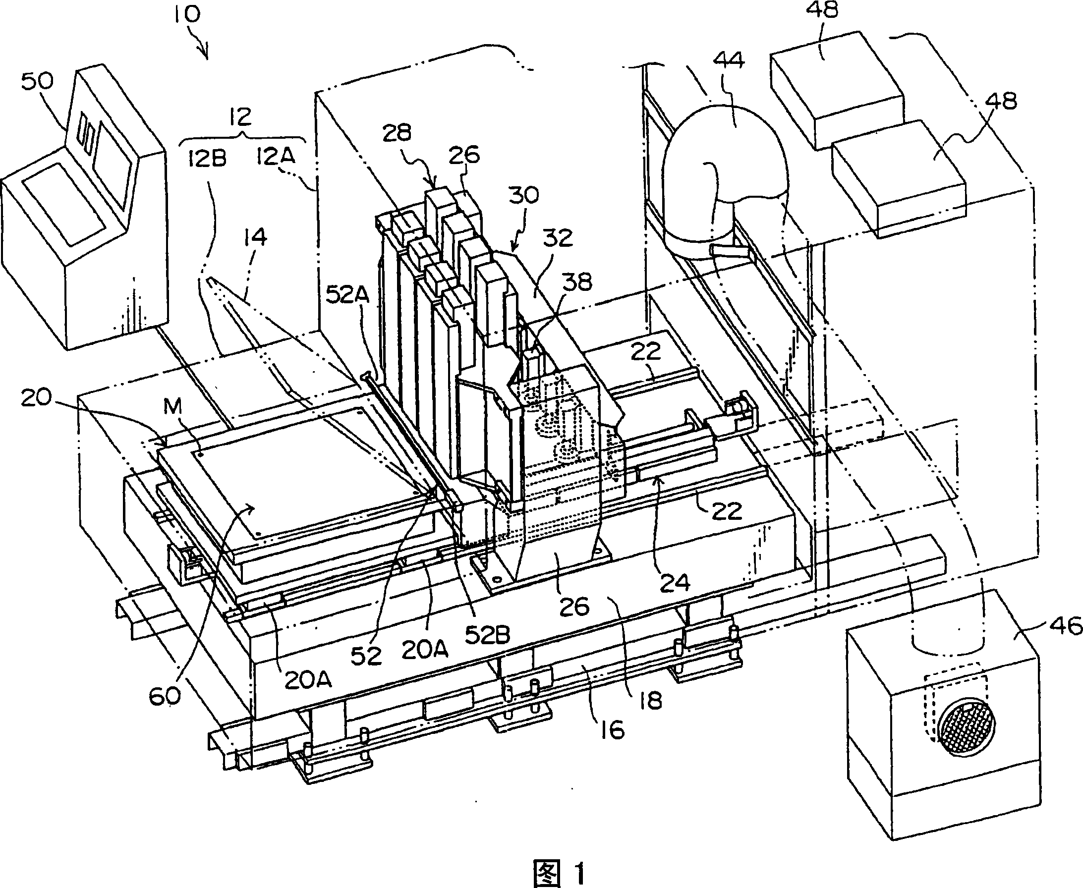
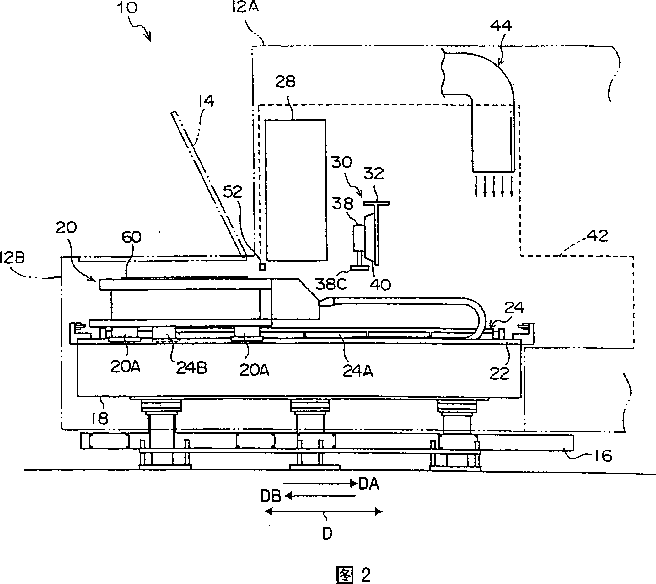
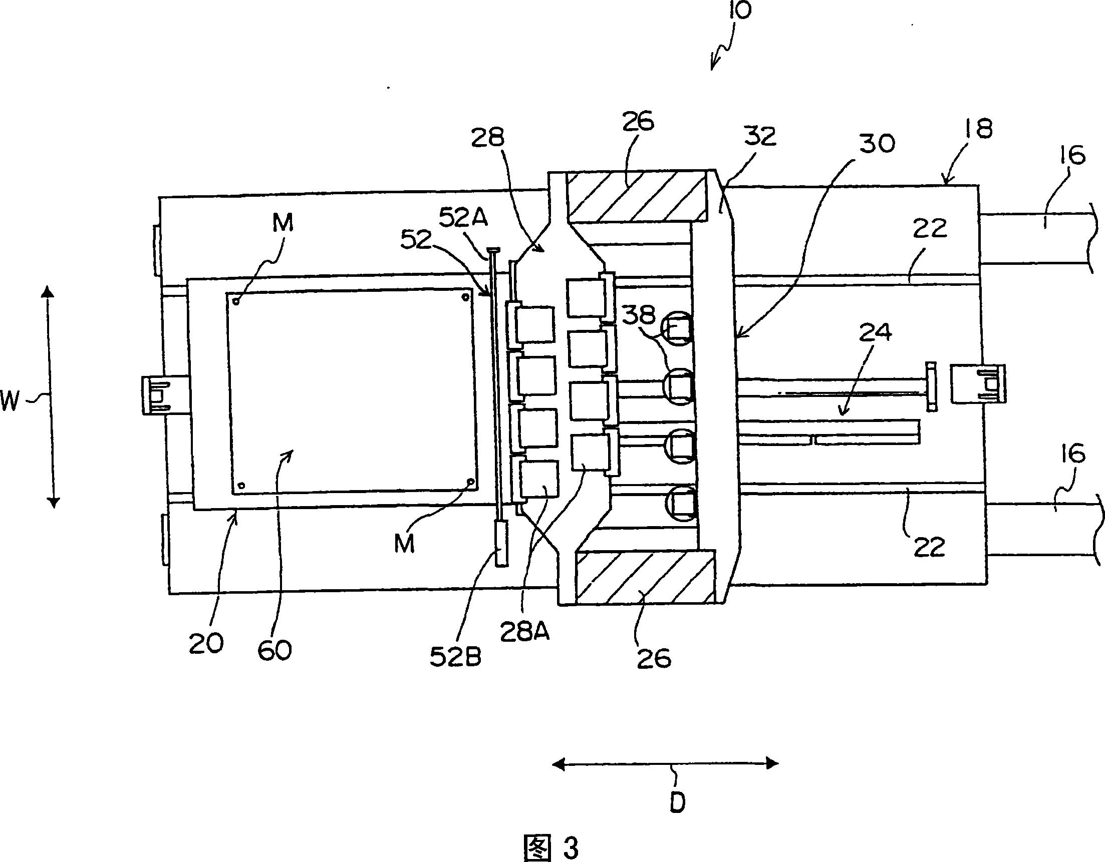
[0051] Hereinafter, the best mode for carrying out the present invention will be described in detail based on the embodiments shown in the drawings. FIG. 1 is a schematic perspective view of the exposure apparatus of the present invention, FIG. 2 is a schematic side view of the exposure apparatus, and FIG. 3 is a schematic plan view of the exposure apparatus. In addition, in FIG. 3, let arrow W be a width direction, and let arrow D be a moving direction or a scanning direction. In FIG. 2 , let the arrow DA be the forward direction, and let the arrow DB be the backward direction.

[0052] (Configuration of Exposure Device)

[0053] As shown in FIGS. 1 to 3 , the exposure apparatus 10 is configured such that each part is accommodated in a rectangular frame 12 formed by assembling rod-shaped square tubes into a frame shape, and a not-shown slab is laid on the frame 12 . panel. Thus, the exposure apparatus 10 has a structure isolated from the outside.

[0054] The frame body 1...


PUM


Abstract

An image position measuring apparatus is provided with a photographing unit, which includes an imaging element and/or a lens and measures the position of a reference mark formed on a work; and a correcting unit for correcting distortion of the imaging element and/or the lens. An exposure apparatus is provided with the image position measuring apparatus and an exposure unit which performs exposure to the work corresponding to the image data corrected based on the positional information of the reference mark photographed by the image position measuring apparatus. Influence of the distortion of the imaging element and the lens can be eliminated, and accuracy of measuring the position of the reference mark given to the work can be improved.

Description

technical field [0001] The present invention relates to an image position measuring device and an exposure device, wherein the image position measuring device has a camera unit for measuring the position of a reference mark formed on a workpiece; The position information of the fiducial mark is used to adjust the position of the image formed on the workpiece. Background technique [0002] Conventionally, for example, a laser exposure apparatus for forming a wiring pattern on a printed wiring board (hereinafter, sometimes referred to as “substrate” or “photosensitive material”) as a workpiece is known. This laser exposure apparatus is equipped with the exposure stage which mounts the printed wiring board which is the object of image exposure, and moves this exposure stage along a predetermined conveyance path. [0003] Specifically, the exposure stage on which the printed wiring board is placed moves in the sub-scanning direction at a predetermined speed, and at a predetermi...

Claims


Application Information

Patent Timeline
Patent Type & Authority Applications(China)
IPC IPC(8): G03F9/00G03F7/20G01B11/00
CPCG03F9/7088G03F7/70791G03F9/00G01B17/025B64D15/20
Inventor 上村宽福井隆史
Owner FUJIFILM CORP
Why Eureka
Try Eureka