Automizing device
A technology of atomization device and container, which is applied in the direction of spraying device, liquid spraying device, fluid using vibration, etc., which can solve the problems of reduced atomization performance, reduced amount of mist, and reduced water supply
- Summary
- Abstract
- Description
- Claims
- Application Information
AI Technical Summary
Problems solved by technology
Method used
Image
Examples
Embodiment approach 1
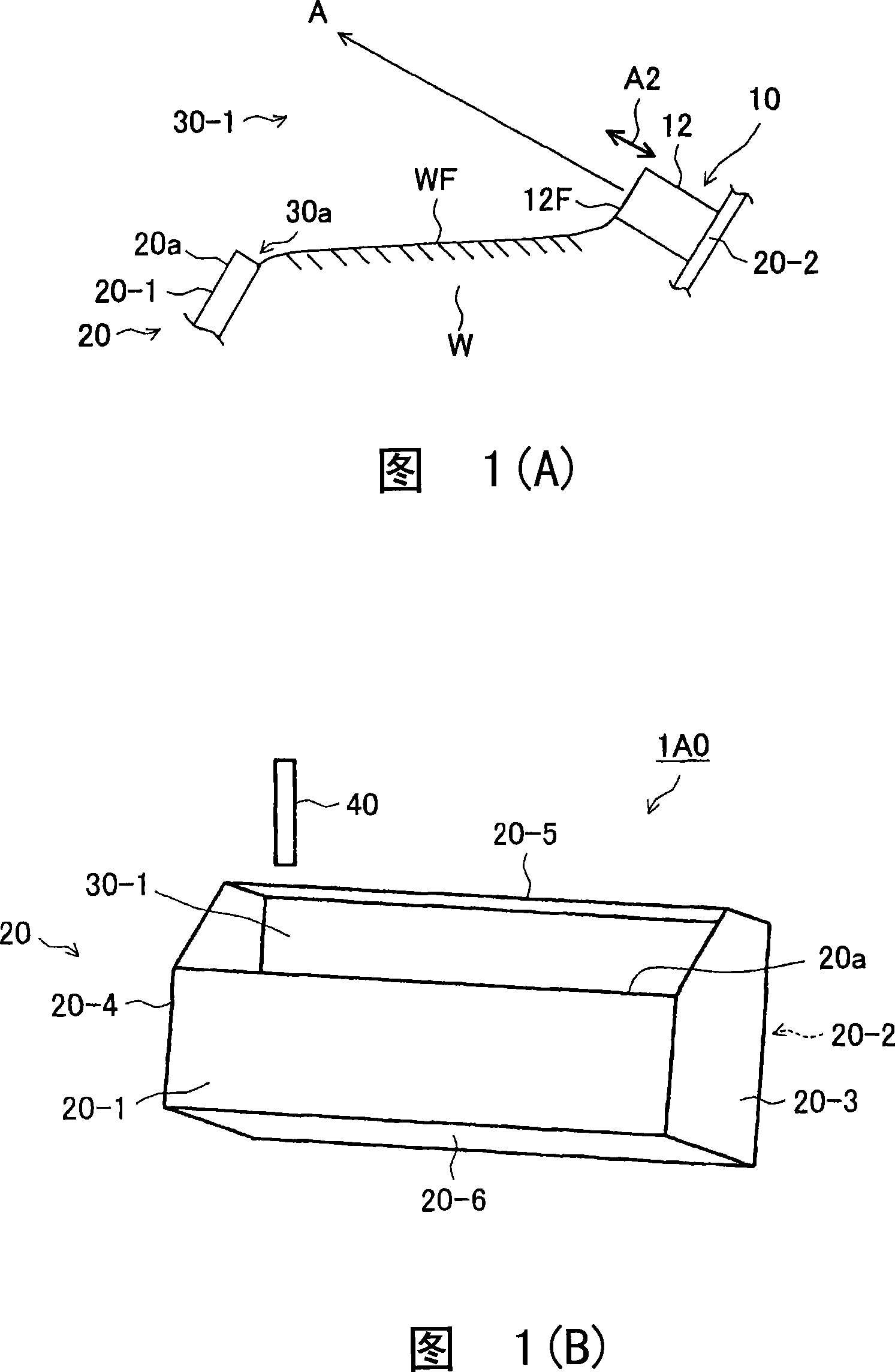
[0154] Embodiment 1 of the atomization device of the present invention is mainly described with reference to FIG. 1(A), but for convenience, part of the composition description refers to FIG. 1(E).
[0155] Fig. 1(A) is a partial cross-sectional view of an atomizing device 1 according to Embodiment 1 for explaining the atomization principle of the atomizing device of the present invention.
[0156] The atomizing device 1 has a piezoelectric vibrator 10 and an upper end portion 20a of a front wall 20-1 that defines a water level WF. Here, the upper end part 20a of the front wall 20-1 is an example of the front end of the liquid level maintenance wall of the atomization device of this invention.
[0157] The atomizing device 1 has a piezoelectric vibrator 10 and a front wall 20-1 including an upper end portion 20a with a predetermined water level WF. In the atomizing device 1, the front wall 20-1 forms an opening 30-1 above as shown in FIG. 1(B), and therefore, the upper end 20...
Embodiment approach 2
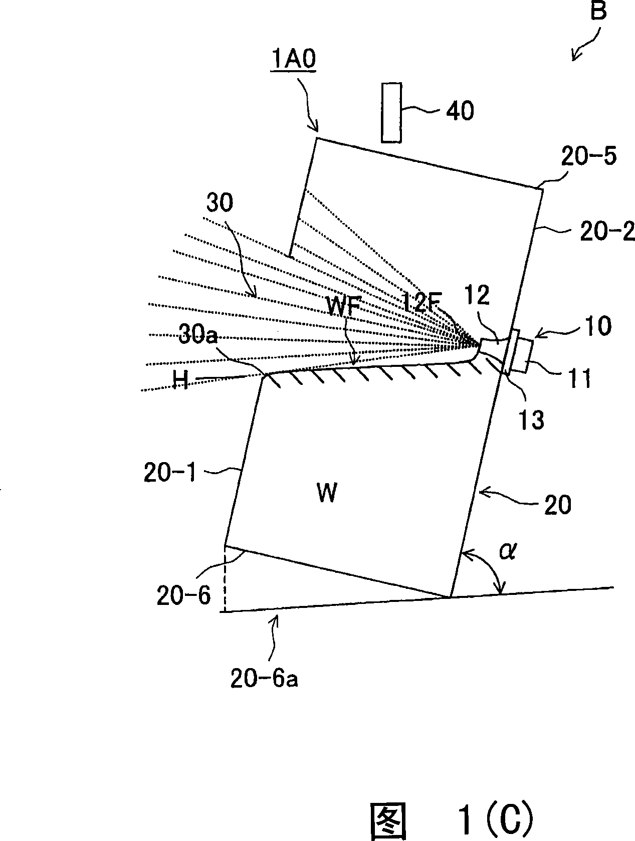
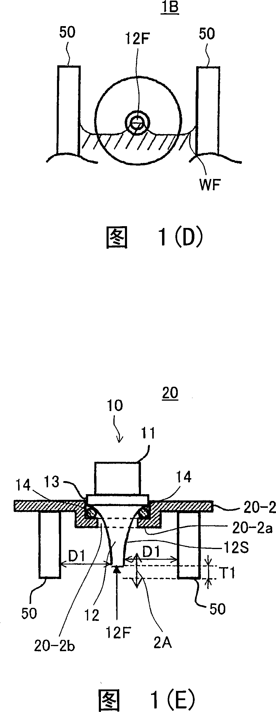
[0186] Embodiment 2 of the present invention will be described with reference to FIGS. 1(B) to (E).
[0187] The atomization device of Embodiment 2 is an atomization device 1A0 to which the atomization principle of Embodiment 1 of the present invention explained with reference to FIG. 1(A) is applied.
[0188] FIG. 1(B) is a perspective view of an atomizing device 1A0 according to Embodiment 2, and FIG. 1(C) is a cross-sectional view illustrating the inside of the atomizing device 1A0 according to Embodiment 2. FIG. 1(D) is a front view showing the configuration of the piezoelectric vibrator 10 and the surface tension assisting member 50 of the atomization device 1A0 illustrated in FIG. 1(C). Fig. 1 (E) is a sectional view seen from the top of the atomizing device 1 showing the arrangement of the piezoelectric vibrator 10, the surface tension auxiliary member (water suction member) 50 and the buffer member 14 illustrated in Fig. 1 (D) .
[0189] The atomization device 1A0 of...
Embodiment approach 3
[0281] 5(A) to (G) are diagrams showing the formation of an atomizing device 1A1 according to Embodiment 3 of the present invention. Atomization device 1A1 of Embodiment 3 is an atomization device that classifies mist generated by atomization and has discharge.
[0282] "Classification" refers to distinguishing mist according to the particle diameter (size) among mist of various particle diameters generated by atomization. Therefore, mist with a particle diameter within a desired range can be used according to the application.
[0283] In addition, the same code|symbol is attached|subjected to the same component unit as Embodiment 1 and Embodiment 2, and it demonstrates.
[0284] The atomizing device 1A1 according to Embodiment 3 has a box-shaped container 20 , a vibrator 10 , a mist discharge and water level maintenance opening 30 - 1 provided on a front wall 20 - 1 capable of classifying mist, and a water replenishment unit 40 . The atomizing device 1A1 also has an excitat...
PUM
 Abstract
Description
Claims
Application Information
 - R&D
- Intellectual Property
- Life Sciences
- Materials
- Tech Scout
- Unparalleled Data Quality
- Higher Quality Content
- 60% Fewer Hallucinations
Browse by: Latest US Patents, China's latest patents, Technical Efficacy Thesaurus, Application Domain, Technology Topic, Popular Technical Reports.
© 2025 PatSnap. All rights reserved.Legal|Privacy policy|Modern Slavery Act Transparency Statement|Sitemap|About US| Contact US: help@patsnap.com


