Independent wheel direct single axis bogie flexible coupling radial adjusting agency

A technology of adjusting mechanism and bogie, which is applied in the self-adjustment of wheel axles, railway couplings, railway car body parts, etc. It can solve the problems of steel spring stability, affecting the normal operation of springs, and troublesome implementation.

Inactive Publication Date: 2008-06-25
SOUTHWEST JIAOTONG UNIV
View PDF1 Cites 9 Cited by
  • Summary
  • Abstract
  • Description
  • Claims
  • Application Information

AI Technical Summary

Problems solved by technology

[0010] (1) In the theoretical derivation of the aforementioned invention patent (patent application number CN200410035861.X), it is assumed that the coupling element only provides longitudinal stiffness, while the stiffness in other directions tends to be zero. This assumption can only be established when the front and rear frames are connected and the longitudinal span of the front and rear hinge points is relatively large. In this way, the stability of the steel spring constrained by spherical hinges at both ends is problematic under stress;
[0011] (2) Such arranging of the spring requires that the steel spring can be both stretched and compressed, so that the positioning and connection parts at both ends of the steel spring will be specially treated, which is troublesome to implement in engineering;
[0012] (3) Both ends of the steel spring are connected to the front and rear frames respectively, and the steel spring will naturally sag under the action of gravity, which will affect the normal operation of the spring

Method used


Image

  • Independent wheel direct single axis bogie flexible coupling radial adjusting agency
  • Independent wheel direct single axis bogie flexible coupling radial adjusting agency
  • Independent wheel direct single axis bogie flexible coupling radial adjusting agency

Examples


Embodiment Construction

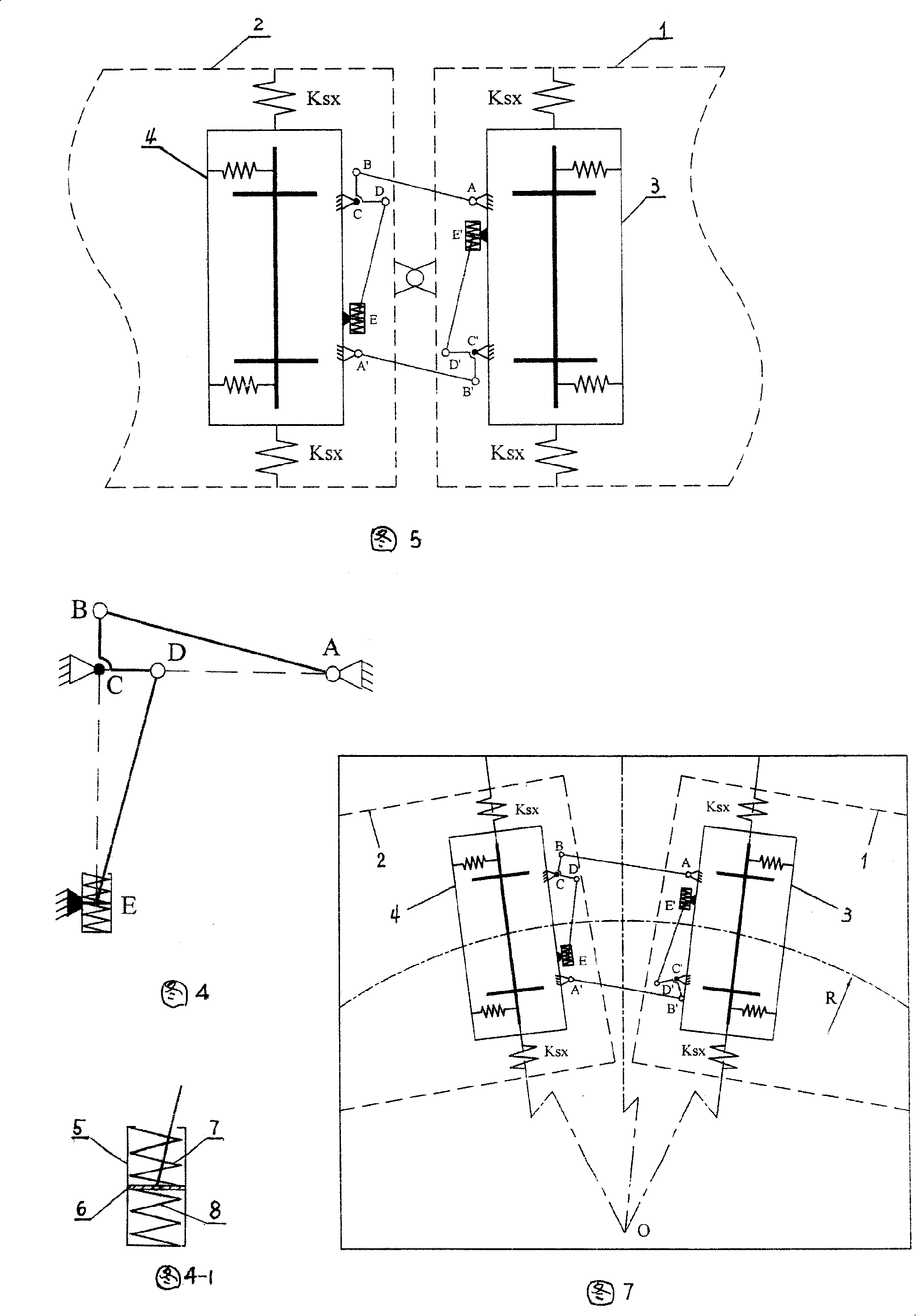
[0049] Figure 4 and Figure 4-1 show that a single elastic coupling mechanism consists of a right-angle arm BCD, a connecting rod AB, a connecting rod DE and a spring device. Wherein the spring device is made up of cylinder barrel 5 (including cylinder head), piston 6 and two springs 7,8 again. The two springs 7 and 8 in the compressed state are respectively placed in the upper and lower cylinder barrel spaces of the piston 6 . Referring to Fig. 5, during installation, the front and rear independent wheel pairs under the adjacent ends of the front and rear car bodies 1 and 2 of the train adopt single-axle bogies, and between the front and rear single-axle bogies 3, 4, before 1. Two identical elastic coupling mechanisms are arranged in such a manner that the hinge points of the rear vehicle body are symmetrical to the center. The structure of a single elastic coupling mechanism is as follows: point C of the right-angle swivel arm BCD is pinned to the rear single-axis bogie 4, t...


PUM


Abstract

The invention relates to an adjusting mechanism for a flexible coupled radial single-axle bogie with independently rotating wheel. Two elastic coupling mechanisms are arranged symmetrically by taking a link joint between a front bodywork and a post bodywork as a center. The structure of one elastic coupling mechanism goes as follows: a C point of a right angle tumbler BCD is pin-connected with a back single-axle bogie; a B end of a link bar AB is connected on the B point of the right angle tumbler BCD through a spherical hinge; an A end of the link bar AB is connected with a front single-axle bogie through the spherical hinge; a D end of a link bar DE is connected with a D end of the right angle tumbler BCD through the spherical hinge; an E end of the link bar DE is connected with a piston in a cylinder barrel through the spherical hinge. Two springs under the state of compression are arranged respectively above and below the piston in the cylinder barrel. The cylinder barrel is fixed on the back single-axle bogie. The length of the link bar AB and the link bar DE is the same. Two arms of the right angle tumbler bear the same length. The adjusting mechanism for a flexible coupled radial single-axle bogie with independently rotating wheel in the invention has the advantages of reasonable structure and good steering capability and solves the steering problem of independently rotating wheel from the engineering application perspective.

Description

technical field [0001] The invention relates to an independent wheel set bogie for railway vehicles, specifically, a flexible coupling radial adjustment mechanism is arranged between the existing independent wheel set single axle bogie to improve the guiding performance of the independent wheel set bogie . Background technique [0002] With the prosperity of the economy and the rapid increase of the urban population, the development prospects of urban rail transit are very promising. Light rail vehicles in urban rail transit usually require low-floor structural requirements, and the bogies of low-floor vehicles usually use independent wheel sets. This is mainly because the left and right wheels of the independent wheel set can freely rotate around the axle without the need to rotate, so the axle of the independent wheel set can be made concave, thereby reducing the height of the vehicle floor. [0003] However, since the left and right wheels of the independent wheel set r...

Claims


Application Information

Patent Timeline
IPC IPC(8): B61G5/02B61F5/38
Inventor 池茂儒张卫华曾京戴焕云邬平波
Owner SOUTHWEST JIAOTONG UNIV
Why Eureka
Try Eureka