
Method and apparatus for viewing hole internal wall image

A technology of hole inner wall and imaging, which is applied in the direction of measuring devices, material analysis through optical means, instruments, etc., can solve the problems of difficult maintenance and high cost, and achieve the effect of labor-saving assembly, simplified structure and less interference

Inactive Publication Date: 2011-09-14
PRECISION MACHINERY RES & DEV CENT
View PDF3 Cites 0 Cited by
  • Summary
  • Abstract
  • Description
  • Claims
  • Application Information

AI Technical Summary

Problems solved by technology

However, this patented technology is very similar to the technical principle of the previous Japanese patent case. It is designed through refraction and reflection and precise angle calculation. It requires high processing accuracy and relatively high cost. It will cause problems that are not easy to maintain in the future

Method used


Image

  • Method and apparatus for viewing hole internal wall image
  • Method and apparatus for viewing hole internal wall image
  • Method and apparatus for viewing hole internal wall image

Examples


Embodiment Construction

[0058] One, the technical concept of the present invention

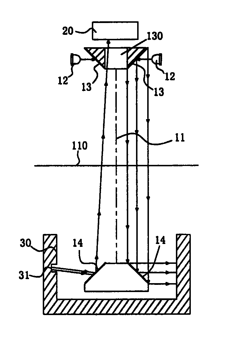
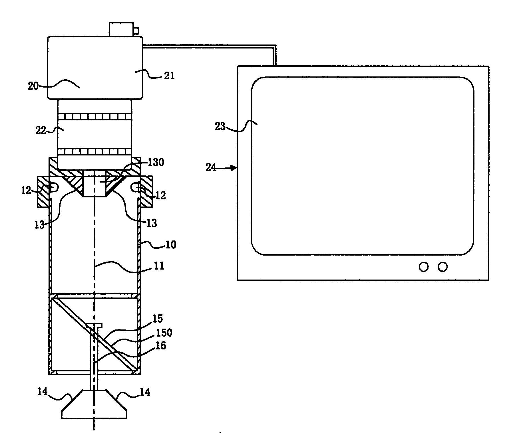
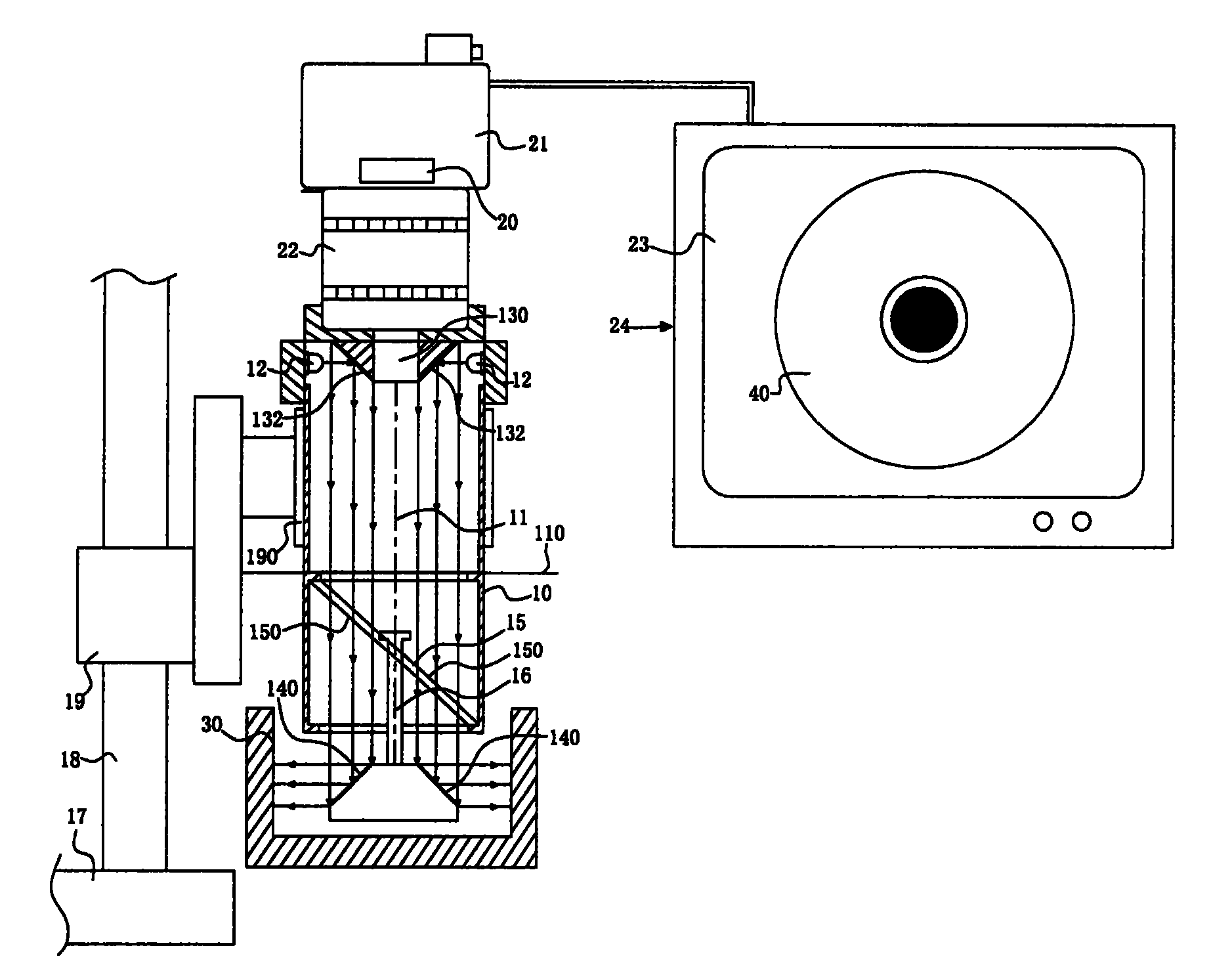
[0059] The main technical concept of the device and method for inspecting the image of the inner wall of the hole in the technical feature of the present invention is to make a special design of the device structure and components to simplify the inspection optical path and the structure of the components, which can not only reduce the cost of component materials, but also facilitate assembly Manufacture and maintenance, and can improve the convenience of inspection.

[0060] In order to facilitate examiners and those who are familiar with the technical field and have ordinary knowledge can truly understand the technical features, effects and goals of the invention, or can be implemented according to the description of the invention, the design principle of the invention , methods and devices for specific implementation and supplemented by diagrams, further detailed descriptions are as follows.

[0061] Two, basic p...


PUM


Abstract

The present invention discloses a method and an apparatus for detecting images in inner wall of a hole; typically, a first reflection surface and a second reflection are arranged on a main body at a fixed interval, and the second reflection surface is moved into the detected hole; a light source projects light beams; after the reflection of the first reflection surface and the second reflection surface, the light beams are projected onto the inner wall of the hole for providing illumination; the second reflection surface positioned in the hole reflects the images of the inner wall of the hole to an image sensor; after the receipt of the image sensor, the image signal is outputted to be used or displayed, so that the light path and structure are simplified, and the purpose of reducing cost and easy maintenance is achieved.

Description

technical field [0001] The present invention relates to a method and device for inspecting the image of the inner wall of a hole, especially a method and device for inspecting the inner wall of a hole by using two corresponding first reflective surfaces and a second reflective surface to conduct light guides to form a simple optical path and simplified structure for inspection of the inner wall of the hole. Technology. Background technique [0002] At present, with the development of industry, the processing accuracy requirements of various products are becoming more and more stringent. In industrial products, the processing of holes is often seen, especially in metal parts, which often require various processing techniques, such as drilling, milling, or chemical etching, to form holes in the metal parts. [0003] During the processing, sometimes due to various factors, such as dust, miscellaneous debris, or poor or unstable processing machines or parts, the inner wall of t...

Claims


Application Information

Patent Timeline
Patent Type & Authority Patents(China)
IPC IPC(8): G01N21/954
Inventor 廖茂钦沈建文
Owner PRECISION MACHINERY RES & DEV CENT
Learn More