Gasket

A technology of gaskets and components, applied in the sealing of engines, sealing devices of engines, machines/engines, etc., can solve problems such as deterioration of sealing performance or durability, and achieve the effect of suppressing deformation and stress concentration

Inactive Publication Date: 2008-06-25
NOK CORP
View PDF3 Cites 7 Cited by
  • Summary
  • Abstract
  • Description
  • Claims
  • Application Information

AI Technical Summary

Problems solved by technology

However, there is a possibility of deteriorating sealing performa

Method used


Image

  • Gasket
  • Gasket
  • Gasket

Examples


no. 1 example

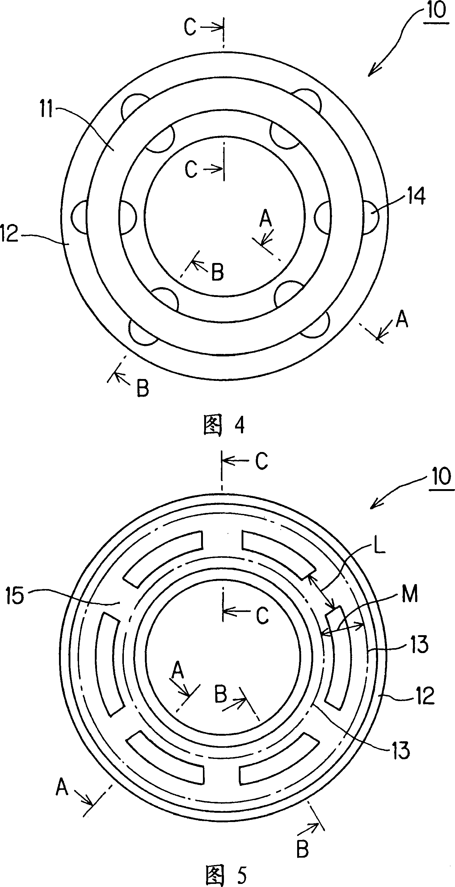
[0064] A gasket according to an embodiment of the present invention will be described in detail below with reference to FIGS. 1 to 12 .

[0065]

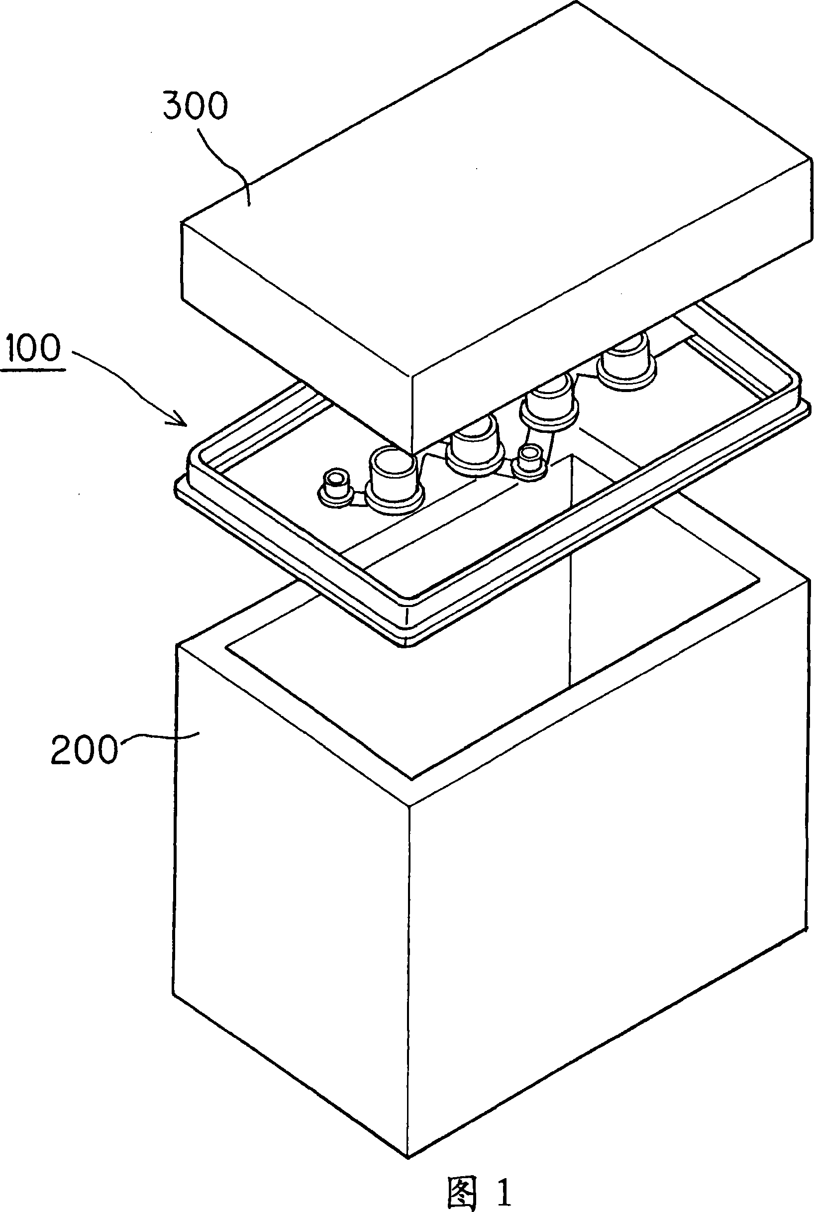
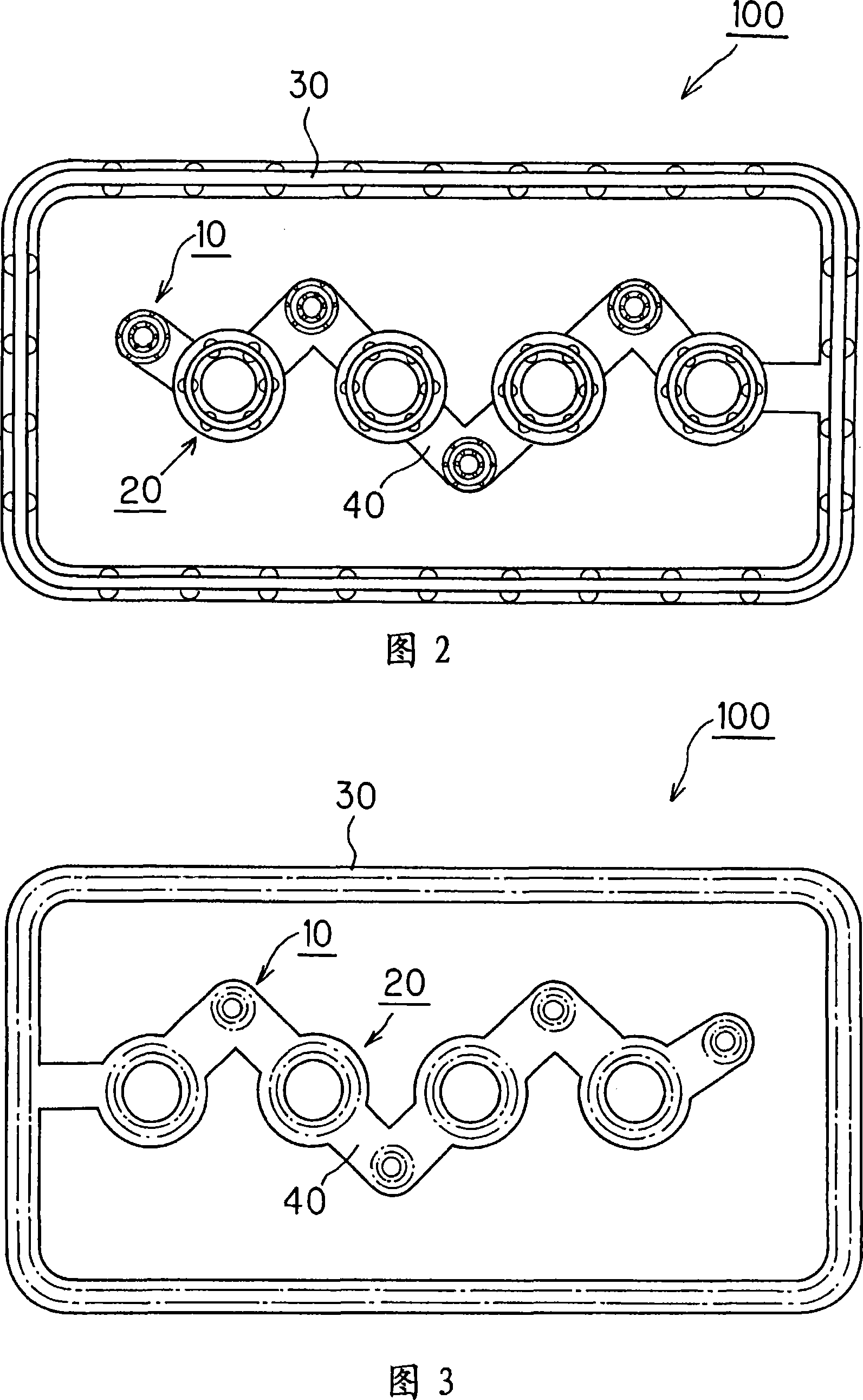
[0066] The complete gasket will be described in detail with reference to FIGS. 1 to 3 in particular. Fig. 1 is an exploded perspective view of components before a gasket is installed; Fig. 2 is a top view of a gasket according to an embodiment of the present invention; Fig. 3 is a bottom view of a gasket according to an embodiment of the present invention.

[0067]The gasket 100 of this embodiment is used to seal the gap between the cylinder head 200 and the cam cover 300 . In FIG. 1 , various components provided in the cylinder head 200 are omitted.

[0068] The gasket 100 includes a first gasket 10 for sealing the ignition coil portion, a second gasket 20 for sealing the ignition coil bolt portion, and a third gasket for sealing the outer frame portion of the cylinder head 200 and the cam cover 300 30, and a joint 40 for conne...


PUM


Abstract

A gasket where a crack is less likely to occur in a seal lip, which improves sealing ability the gasket. A first gasket (10) is installed in a groove formed in a cam cover and seals the gap between a cylinder head and a cam cover. The first gasket has a pair of parallel seal lips (13) in intimate contact with a cylinder head and also has connection sections (15) arranged between the pair of seal lips (13). The connection sections (15) are connected to each of the seal lips (13) and retain, in the vicinity of the connections, the spacing between the seal lips (13).

Description

technical field [0001] The invention relates to a gasket for sealing a gap between two parts. Background technique [0002] An example of a conventional gasket for sealing a gap between two members will be described below with reference to FIGS. 13 to 15. FIG. Fig. 13 is a plan view of a conventional gasket. Fig. 14 is a schematic sectional view of a conventional gasket in an assembled state. The gasket shown in FIG. 14 corresponds to the cross-sectional view taken along line D-D in FIG. 13 . Fig. 15 is a graph showing the relationship between the squeeze ratio and the inter-flange stretch ratio of a conventional gasket. [0003] The conventional example shown is a gasket 500 for sealing the gap between the cylinder head 200 and the cam cover 300 . The spacer 500 is seated in a groove 301 formed in the cam cover 300 . Pairs of protrusions 501 are provided on a side surface of the main body of the spacer 500 spaced apart from each other by a predetermined distance. The ...

Claims


Application Information

Patent Timeline
IPC IPC(8): F16J15/10
CPCF16J15/106F02F11/007F16J15/061
Inventor 松本共永中尾孝志义经修司武野一记
Owner NOK CORP
Why Eureka
Try Eureka