Working roll consideration to strip steel convexity, edge drop control and abrasion control and using method

A wear control and strip crown technology, applied in the direction of manufacturing tools, profile control, rolls, etc., can solve the problem of no crown control function, improve the stability control effect, facilitate the popularization and application, and improve the non-oriented silicon steel crown. The effect of degree control

Inactive Publication Date: 2008-07-09
WUHAN IRON & STEEL (GROUP) CORP +1
View PDF0 Cites 26 Cited by
  • Summary
  • Abstract
  • Description
  • Claims
  • Application Information

AI Technical Summary

Problems solved by technology

The online roller grinding device is directly installed on the rolling mill frame, which can mode

Method used


Image

  • Working roll consideration to strip steel convexity, edge drop control and abrasion control and using method
  • Working roll consideration to strip steel convexity, edge drop control and abrasion control and using method
  • Working roll consideration to strip steel convexity, edge drop control and abrasion control and using method

Examples


specific Embodiment approach 1

[0043] This embodiment provides a work roll that is used when rolling 2.3mm×1050mm low-grade non-oriented silicon steel with a 1700 hot continuous rolling mill, taking into account strip crown, edge drop control and wear control.

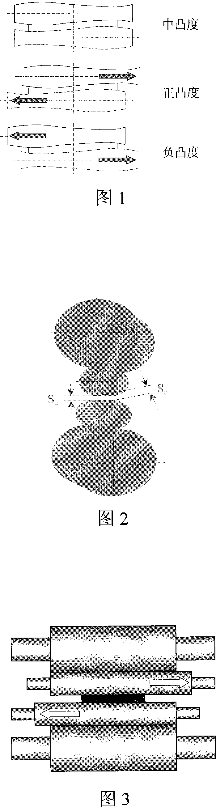
[0044] 1700 hot continuous rolling mill F5 stand has a work roll body length of 2000mm and a roll body diameter range of 760mm to 700mm. The roll shape curves of the upper and lower work rolls are the same, but they are placed at an opposite angle of 180°. We call it ASR-Y here. (asymmetry self-compensating work rolls for Yrolling campaign) asymmetric self-compensating work rolls.

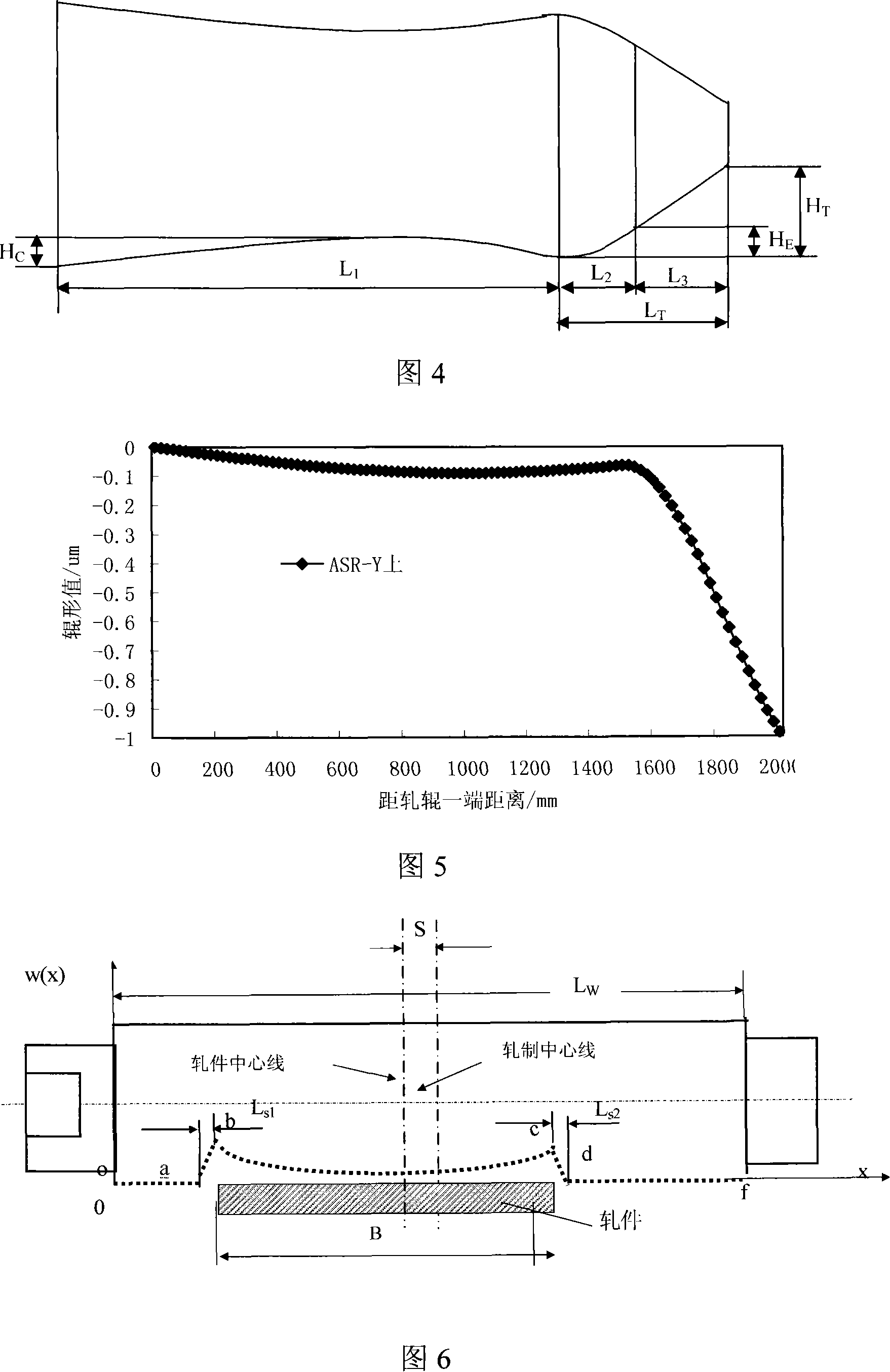
[0045] The above work roll is taken as an example. The ASR-Y upper work roll is composed of three parts according to the length direction, that is, the length of the crown control section L 1 , edge drop and wear control section length L 2 , the length of the structural process section L 3 (refer to Figure 4);

[0046] The equations for determining the roll curves of ...

specific Embodiment approach 2

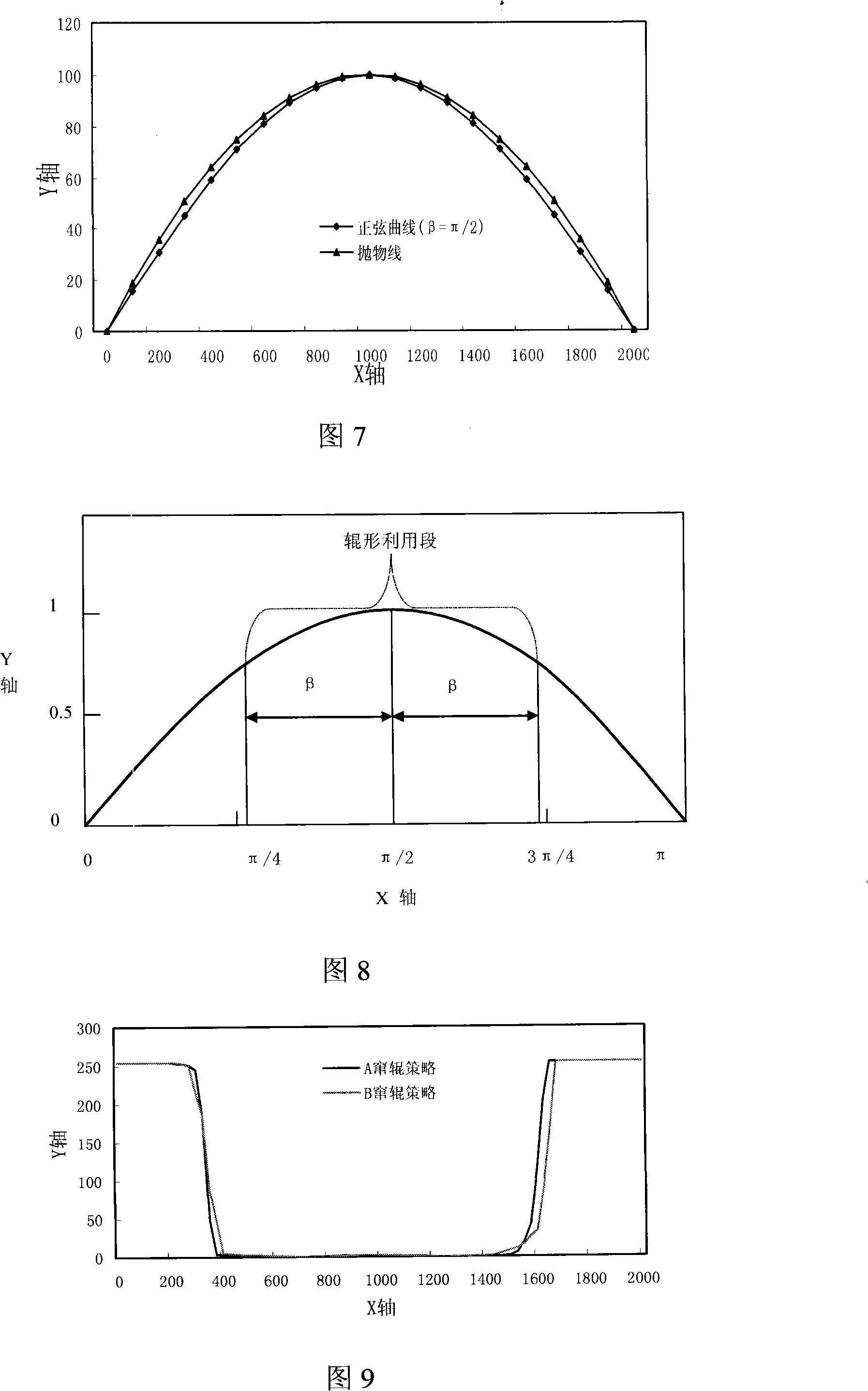
[0103] Convexity control segment length L 1 Part of the roll shape curve can also adopt ordinary parabolic roll shape y = H C [ 1 - ( 2 x L W - 1 ) 2 ] , See Figure 7, (see Remn-Min Guo, Characteristics of rolling mills with roll shifting, Iron and steelengineer, 1988, 65(12): 45-54) plus the hot roll shape stability component established by the hot rolling rolling unit (see Zhang Jie , Zhang Xuanli, Cao Jianguo, et al. Parameter optimization model of work roll temperature field based on genetic algorithm, Metallurgical Equipment, 2003, (4): 4-7; Ginzburg V B, High-Quality SteelRolling: Theory and Practice, Marcel Dekker, New York , 1993: 488-528)...


PUM


Abstract

The invention provides a working roll provided with three functions of convexity control, edge-dropping control and abrasion control and a use method. The working roll has three roll shapes of convexity control segment, edge-dropping and abrasion control segment and structural and technological segment that are identified by three formulas. If the working roll of the invention and a cooperative use method are adopted, the size of band steel edge-dropping area and the amount of edge dropping will be greatly decreased, which are favorable for the decreasing of whole convexity, which is also known as lateral thickness difference. The invention evidently improves the rate of low-convexity band steel. Industrial tests show that the rate of band steel outlet convexity, C 40 of which is less than 52 Mu m, increases form 13.7 per cent to 81.25 per cent after rolling. In addition, the invention effectively controls the quantity of over-standard coil. The rate of band steel with convexity more than 60 Mu m drops to 6.60 percent from 65.6 per cent. When the working roll provided by the invention is not only for stable industrial application, but for continuous and overall application, the rate of on-oriented steel with the size of 2.3mm multiplied by 1050mm will increase from 42.05 per cent to 93.15 percent, which is beneficial to popularizing.

Description

technical field [0001] The invention relates to a work roll used for strip shape control in the production of a hot continuous rolling mill for wide strip steel and a method for using the work roll. Background technique [0002] In the hot continuous rolling of wide strip steel, due to the initial roll shape, roll bending deformation, thermal crown, wear and other reasons, a large overall crown of the strip will inevitably occur. At the same time, the serious wear of the work roll groove "∪" in the downstream stand often causes the strip crown to be too large in the middle and later stages of the rolling unit, especially the edge drop is significant, thus reducing the number of rolled strips in the rolling unit , strip crown and edge drop are difficult to control. The key to flatness control in hot strip mills is that the downstream stand must have dual capabilities of crown control and wear control. In order to improve the lateral thickness difference of hot-rolled finish...

Claims


Application Information

Patent Timeline
IPC IPC(8): B21B27/02B21B37/28
Inventor 宋平曹建国张杰苏毅魏钢城鄢檀力蔡延擘陈良饶克峰唐本立
Owner WUHAN IRON & STEEL (GROUP) CORP
Why Eureka
Try Eureka