Improved forwarding antenna for point-to-point application

A forwarding antenna, point-to-point technology, applied in directions such as antenna arrays, antennas, and antenna arrays that are individually powered, and can solve problems such as low directivity and high loss

Active Publication Date: 2008-07-09
TELEFON AB LM ERICSSON (PUBL)
View PDF0 Cites 14 Cited by
  • Summary
  • Abstract
  • Description
  • Claims
  • Application Information

AI Technical Summary

Problems solved by technology

Such a transponder has many disadvantages, such as high losses due to low directivity, and is generally not suitable for use in urban areas

Method used


Image

  • Improved forwarding antenna for point-to-point application
  • Improved forwarding antenna for point-to-point application
  • Improved forwarding antenna for point-to-point application

Examples


Embodiment Construction

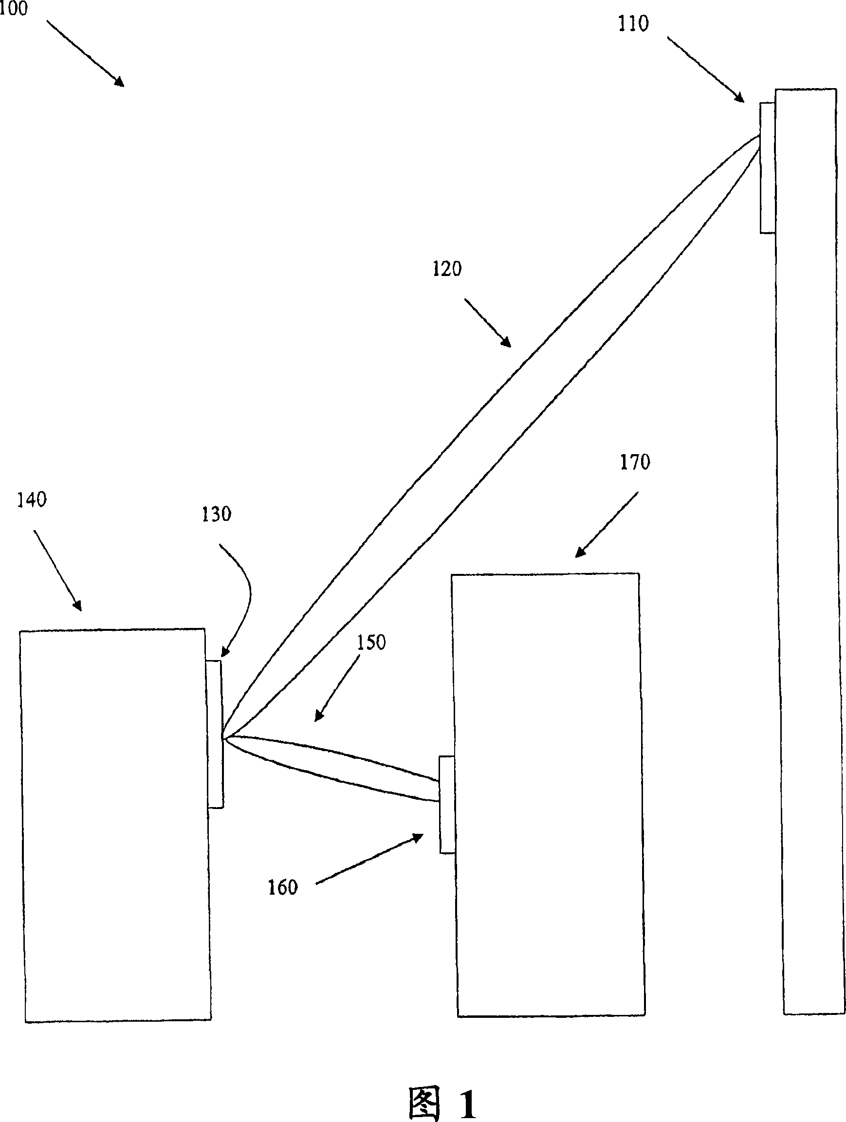
[0013] Fig. 1 shows a system 100 in which the transponder antenna of the present invention can be used. The system 100 shown is a cellular telephone system, which should only be seen as an example to help illustrate the embodiments of the present invention. As known to those skilled in the art, the repeating antenna can be used in a large number of other applications.

[0014] The first radio unit 110 (in this case, a radio base station) in the cellular system 100 cannot provide sufficient service to a certain area in its cell because the building 170 hinders the radio coverage of the area by the base station 110.

[0015] In order to serve the obstructed area, the second radio unit or base station 160 is deployed on the building 170 so that the antenna of the base station 160 can cover the obstructed area. The second radio unit 160 may be a base station similar to the base station 110, but it may also be a base station with a reduced capacity compared to the base station 110, tha...


PUM


Abstract

The invention discloses a repeater antenna for use in point-to-point applications in telecommunications systems in the microwave range, intended for connecting transmissions from a first radio unit at a first site to a second radio unit at a second site. The repeater antenna is essentially plane, and is designed as a traveling wave antenna with at least a first and a second antenna beam, so that the first beam can be used for transmissions to and from said first radio unit, and the second beam can be used for transmissions to and from said second radio unit.

Description

Technical field [0001] The present invention discloses a repeating antenna for point-to-point applications of telecommunication systems in the microwave range. The repeating antenna is used to connect transmission from a first radio unit at a first site to a second radio unit at a second site. Background technique [0002] In a telecommunications system within the microwave range, such as a cellular phone system, there may be many problems when a base station attempts to communicate with users located in the coverage area of ​​the base station. In urban areas, examples of such problems may be high-rise buildings obstructing the line of sight to certain sub-areas, or in certain sub-areas, the density of users may exceed the extent that the base station can handle. [0003] One way to deal with these problems is to install other base stations that can cover the sub-area of ​​interest, usually base stations with smaller capacity, so-called "pico stations." These "pico stations" need...

Claims


Application Information

Patent Timeline
Patent Type & Authority Applications(China)
IPC IPC(8): H01Q13/20H01Q11/02H01Q21/06H04B7/155
CPCH01Q25/004H01Q21/08H01Q21/065H01Q13/206H04B7/1555H01Q11/02H01Q13/20H01Q21/06H04B7/155
Inventor M·安德森P·哈尔比约纳A·里德伯格
Owner TELEFON AB LM ERICSSON (PUBL)
Why Eureka
Try Eureka