Microwave range using microwave as heating source

A microwave cooker and microwave technology, which is applied in the application expansion field of microwave absorbing materials, can solve the problems of inability to realize frying, frying, frying and other production methods, and achieve the effects of simple structure, safe use and reliable use.

Inactive Publication Date: 2008-03-12
马新元 +1
View PDF0 Cites 10 Cited by
  • Summary
  • Abstract
  • Description
  • Claims
  • Application Information

AI Technical Summary

Problems solved by technology

Thereby can't realize the preparation methods such as frying, frying, decocting of Chinese dish

Method used


Image

  • Microwave range using microwave as heating source
  • Microwave range using microwave as heating source
  • Microwave range using microwave as heating source

Examples


Embodiment 1

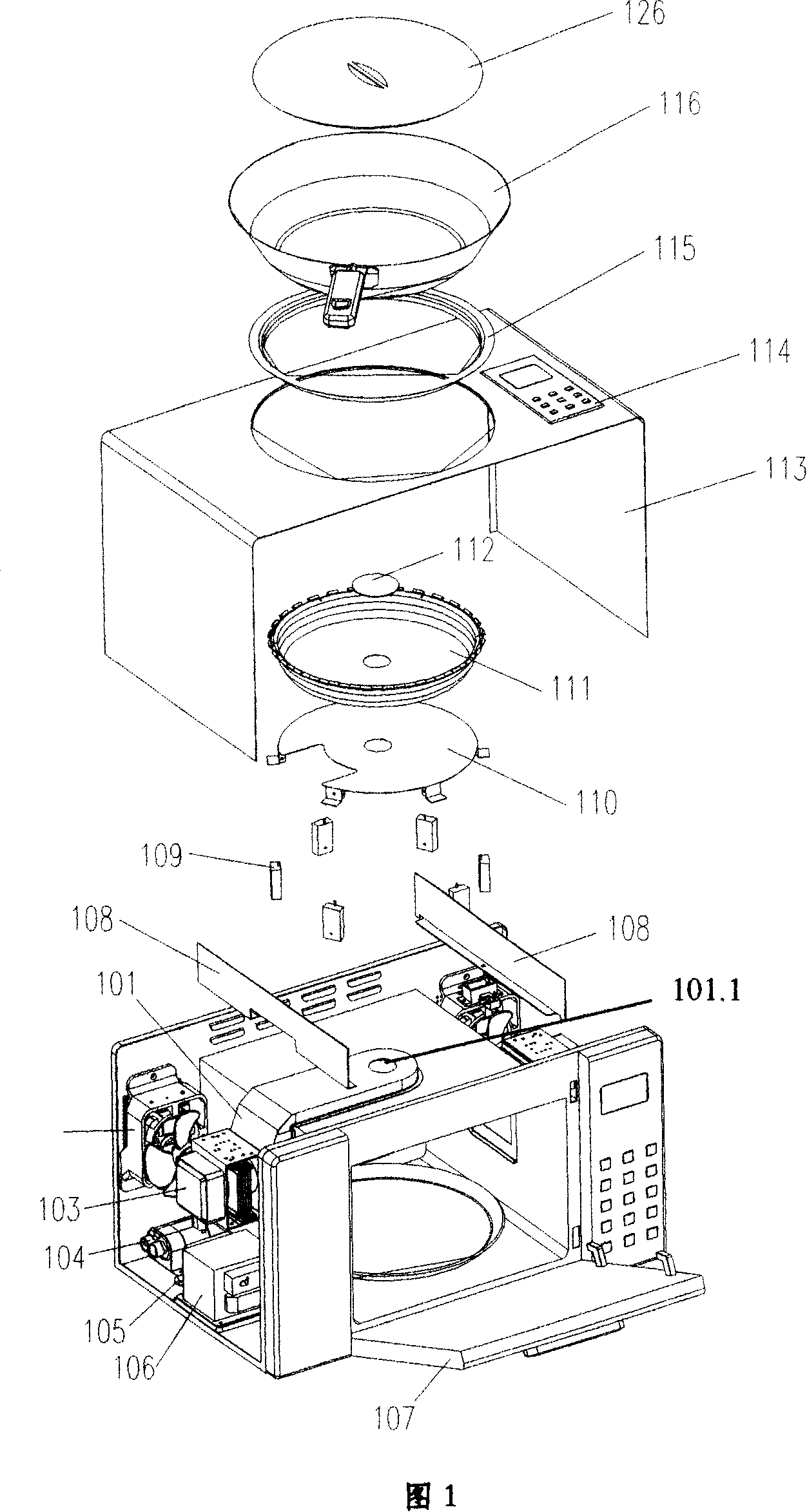
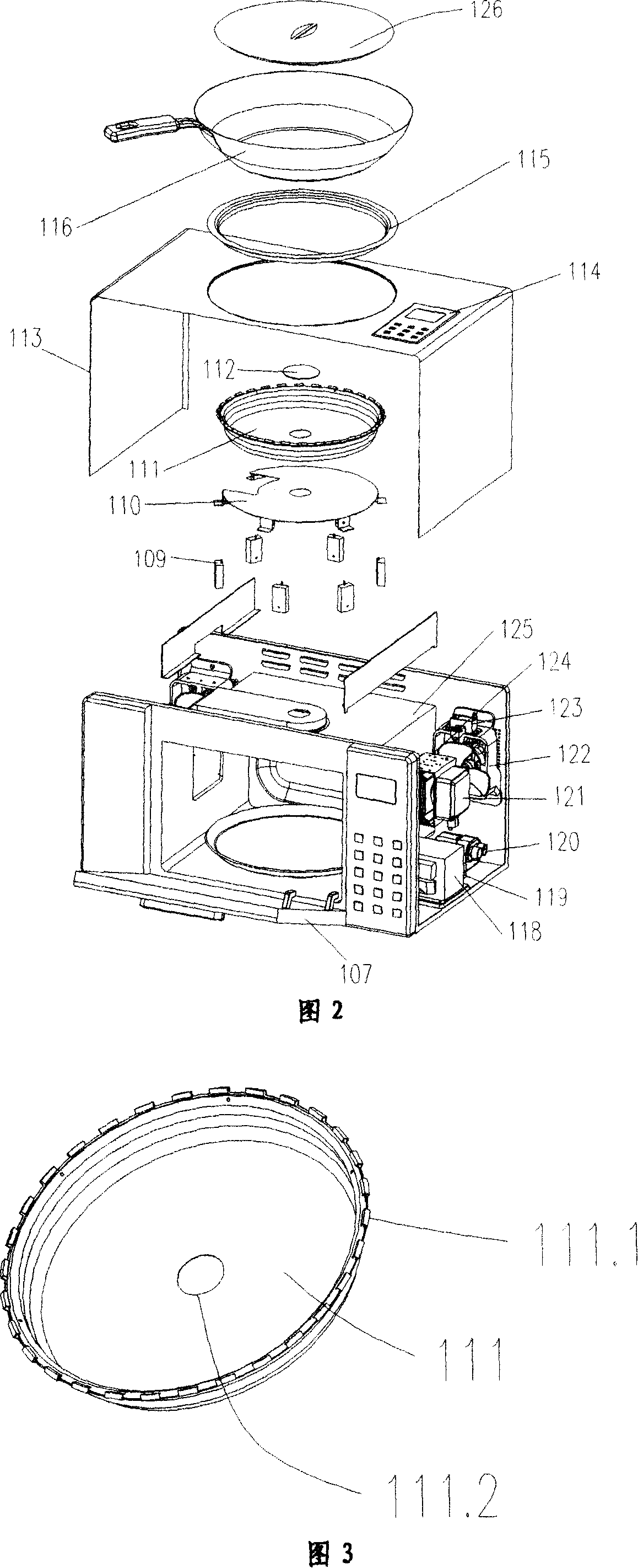
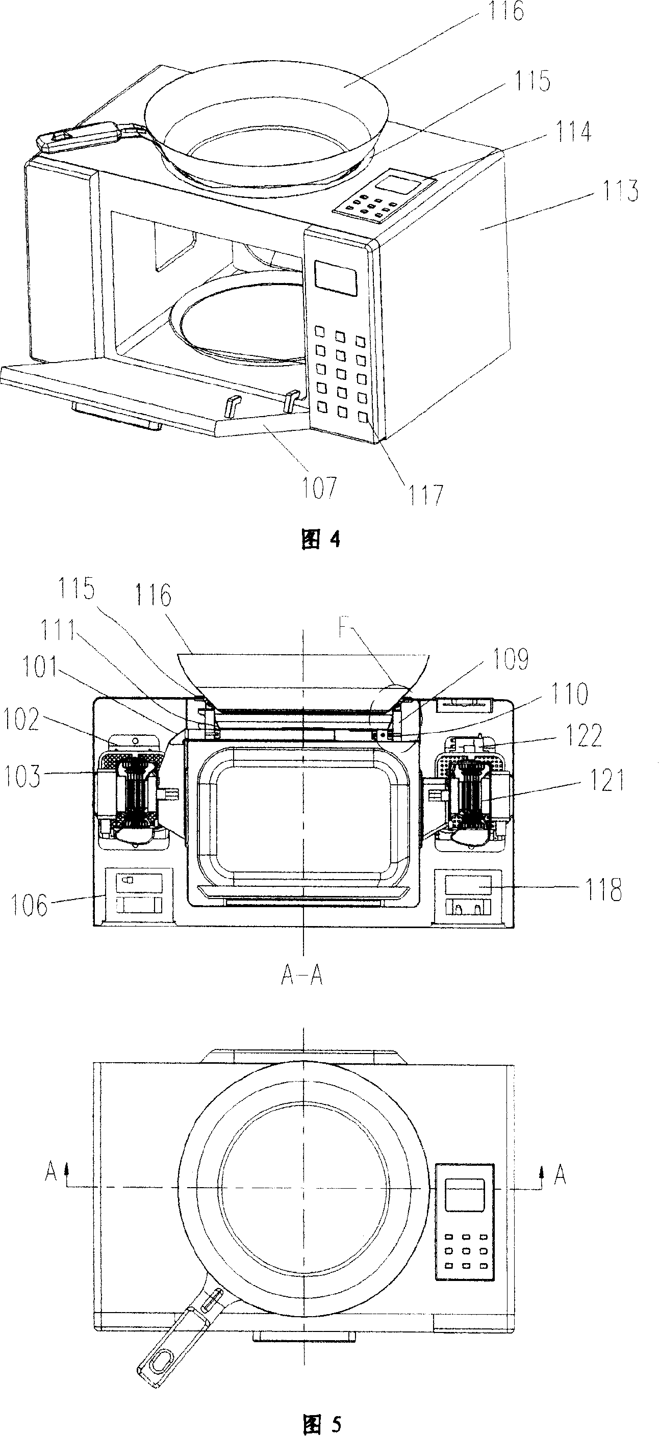
[0022] The basic structure of the patent of the present invention is shown in Figure 1 and Figure 2, including a control computer board 117, a transformer 118, a high voltage fuse 119, a high voltage capacitor 120, a magnetron 122, a furnace chamber waveguide assembly 124, a furnace chamber assembly 125, etc. A microwave direct heating system composed of a magnetron 103, a stove cavity component 111, a stove cavity waveguide component 101, a micro-touch control component bracket 110, a high-voltage capacitor 104, a high-voltage fuse 105, a transformer 106, A heating system composed of a micro-touch control assembly 109, a retaining ring 115, a microwave oven 116, a computer control unit 114, and a baffle 108. Wherein the baffle plate 108 is placed between the furnace cavity assembly 125 and the outer cover 113; the micro-touch control assembly 109 is placed on the micro-touch control assembly bracket 110, and the micro-touch control assembly bracket 110 is provided with the ins...

Embodiment 2

[0024] The basic structure of the patent of the present invention is the same as that of Embodiment 1, except that the microwave oven control computer board 114 and the microwave oven control computer board 117 are combined into one, and only one control computer board is used to control the microwave oven and the microwave oven. The control computer board can be placed at any one of the above-mentioned two control computer board positions.

Embodiment 3

[0026] The basic structure of the patent of the present invention is the same as that of Embodiment 1, except that the micro-touch control component bracket 110 is fixed on the cooking cavity waveguide component 101 or the cooking cavity component 111 or between the two.

[0027] Example 3:

[0028] The basic structure of the patent of the present invention is the same as that of Embodiment 1, except that the cooking cavity assembly 111 is placed directly above the cavity assembly 125, while the cooking cavity waveguide assembly 101 is placed above the cavity assembly 125 and on the side of the cooking cavity assembly 111 .


PUM


Abstract

The invention relates to a microwave oven taking the microwave energy as the heating source, which realizes the functions of implementing the really significant fry, stir-fry, etc. with the microwave through the form of increasing a sub-chamber on the basis of the existing microwave oven and through the adoption of heat energy conversion principle of the microwave. The invention comprises a magnetron for producing the microwave, a waveguide, a resonant chamber and a wave absorbing boiler, and the microwave energy is converted into the heat energy through the wave absorbing boiler; the wave absorbing boiler is independent and open, and one of components of the resonant chamber.

Description

1. Technical field: [0001] The invention is developed aiming at solving the problem that the existing microwave ovens cannot realize the cooking methods of Chinese dishes such as frying, frying and deep-frying. It belongs to the technological innovation of the microwave oven industry and also belongs to the application expansion of microwave absorbing materials. 2. Technical background: [0002] Existing microwave oven structure as shown in Figure 8, mainly comprises oven chamber assembly (125), magnetron (121), high-voltage capacitor (120), high-voltage transformer (118), high-voltage fuse (119), oven door assembly (107 ), a cavity waveguide assembly (127), etc., this type of microwave oven only utilizes the dielectric induction heating effect of microwaves to directly heat the food placed in the oven cavity assembly (125). Thereby can't realize the preparation methods such as frying, frying, decocting of Chinese dishes. [0003] 3. Explanation of reference signs in the m...

Claims


Application Information

Patent Timeline
Patent Type & Authority Applications(China)
IPC IPC(8): F24C7/02F24C7/06F24C7/08F24C15/36A47J27/00
Inventor 马新元
Owner 马新元
Why Eureka
Try Eureka