Radio frequency and microwave signals

a radio frequency and microwave technology, applied in the field of radio frequency and microwave signals, can solve the problems of inherently low ratio of microwave energy produced to the energy stored in the coil, limited amount of energy and power that can be converted to a microwave signal, etc., and achieve the effects of increasing the energy that can be radiated by the antenna, increasing the radiated field, and strong gyromagnetic characteristics

Inactive Publication Date: 2009-03-03
BAE SYSTEMS PLC
View PDF37 Cites 10 Cited by
  • Summary
  • Abstract
  • Description
  • Claims
  • Application Information

AI Technical Summary

Benefits of technology

[0010]It has been found that modulating the video pulse at a suitable frequency produces a modulated pulse having a significant energy content shift to the radio and / or microwave frequencies, representing a major increase in the energy that can be radiated by the antenna. Thus the modulation to the waveform allows the radiated signal to be focused to a greater degree and increases the radiated field that can be produced at a large distance from the source.
[0015]The impulse generator may produce a pumping impulse. This design allows a physically and electrically extended interaction to be achieved between the pumping signal and the magnetic material. The advantages of this scheme are that a significantly larger volume of magnetic material can be excited by a travelling wave in a transmission line, and the energy in the pumping pulse is used more effectively. As a consequence the energy conversion efficiency of this device is considerably higher than that achieved by the prior art. The RF signal and / or microwave signal that is generated by gyromagnetic precession in the magnetic material is supported by the transmission line and appears as a modulation on the pumping video pulse; consequently a separate waveguide is not required to extract the RF and / or microwave signal.
[0017]An external magnetic field may be applied to the transmission line. This magnetic field may have components axially or otherwise orientated to the transmission line. Preferably the transmission line comprises low dielectric loss insulators such as polytetrafluroethylene (PTFE) or polypropylene. The transmission line may have conductors made from copper, silver or gold or other high conductivity materials to minimise resistive dissipation.

Problems solved by technology

Disadvantages of this method of generation of microwave signals include; the amount of energy and power that can be converted to a microwave signal is limited by the requirement for a small spherical specimen of magnetic material, usually YIG, to achieve fully temporally and spatially coherent precession and, because the pulsed magnetic field is produced by passing a large pulsed current through an external coil, the ratio of microwave energy produced to the energy stored in the coil is inherently low, as the pulsed magnetic field is applied to a large volume compared to the volume of the sphere.

Method used


Image

  • Radio frequency and microwave signals
  • Radio frequency and microwave signals
  • Radio frequency and microwave signals

Examples


Embodiment Construction

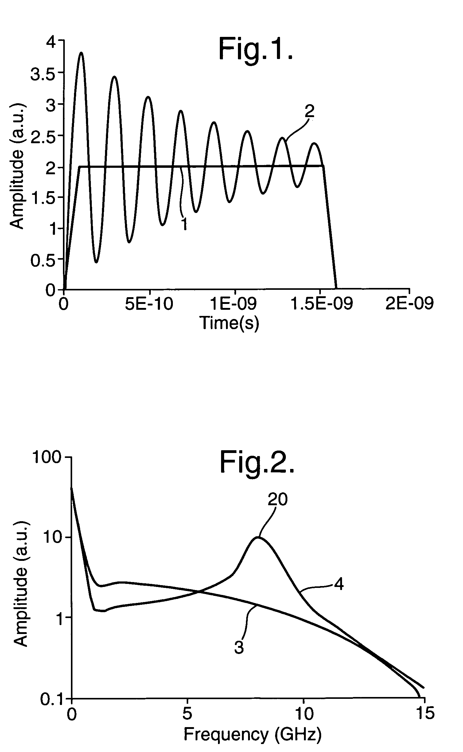
[0029]FIG. 1 compares the time waveform of a typical electrical video impulse 1, with a 0.1 ns rise time and a 1.5 ns pulse duration and the time waveform of a microwave modulated pulse 2. The electrical video pulse might typically be used to drive a UWB antenna directly. FIG. 2 shows the Fourier spectrums of the unmodulated video pulse waveform 3, and microwave modulated waveform 4. From FIG. 2 it can be seen that the majority of energy in the video pulse 1 is contained in spectral components below the 100 MHz region and that there is very little energy in the higher frequency components. Thus a large portion of the components of the video pulse would not be radiated by an antenna because most of the components would have a frequency below the cut-off of the antenna.

[0030]However, the Fourier spectrum of the modulated waveform 4 shows a major peak 20 at the modulation frequency. This represents energy shifted from the video frequencies up to the microwave frequencies and a major in...


PUM


Abstract

A device for generating high powered Radio Frequency (RF) or microwave signals comprising a fast rise-time video pulse generator, a modulator to modify the generated UWB pulses by gyromagnetic action to transfer a portion of the UWB pulse energy from lower frequencies to frequencies in the RF or microwave range thereby producing a resultant RF or microwave waveform that can be radiated.

Description

BACKGROUND OF THE INVENTION[0001]1. Field of the Invention[0002]This invention relates to Radio Frequency (RF) and microwave signals and in particular the generation of high power microwave signals for use in high resolution radar and Directed Energy applications. Because microwave signals fall within the range of RF frequencies, all subsequent references to “RF or microwave signals” and “RF and / or microwave signals” are intended to mean a reference to Radio Frequency signals.[0003]2. Discussion of Prior Art[0004]Shaw H. J., Elliott, B. J., Harker K. J., and Karp A., Microwave generation in pulsed ferrites, J. App. Phys., Vol 37, No. 3, 1966 details a method for converting energy from a pulsed magnetic field to a microwave signal in a waveguide. Shaw's ‘Pulsed Magnetic Microwave Generator’ relies on impulse-driven gyromagnetic precession in a small Yttrium Iron Garnet (YIG) sphere to convert energy from a ‘pump pulse’ to a microwave signal. A small spherical (approximately 1 mm diam...

Claims


Application Information

Patent Timeline
Patent Type & Authority Patents(United States)
IPC IPC(8): G01S7/282H03B19/00G01S13/00
CPCG01S7/282
Inventor SEDDON, NIGELDOLAN, JOHN E
Owner BAE SYSTEMS PLC
Why Eureka
Try Eureka