Needle jack having needle selecting function

A technology of needle jacks and needle selection, which is applied in knitting, weft knitting, textiles and papermaking, etc. It can solve the problems of complex machine head structure, large body size, and large needle plate size, so as to reduce consumables and size The effect of reducing and reducing manufacturing costs

Inactive Publication Date: 2008-07-23
冯加林 +1
View PDF0 Cites 5 Cited by
  • Summary
  • Abstract
  • Description
  • Claims
  • Application Information

AI Technical Summary

Problems solved by technology

The number of auxiliary stitches is large, which makes the length of the needle groove relatively long, and the size of the needle plate is also relatively large, so that the body size of the whole knitting machine is large and the consumables are more; at the same time, the machine head should be supplemented with various The pressure plate mechanism m

Method used


Image

  • Needle jack having needle selecting function
  • Needle jack having needle selecting function

Examples


Embodiment Construction

[0015] The utility model will be further described below in conjunction with accompanying drawings and embodiments.

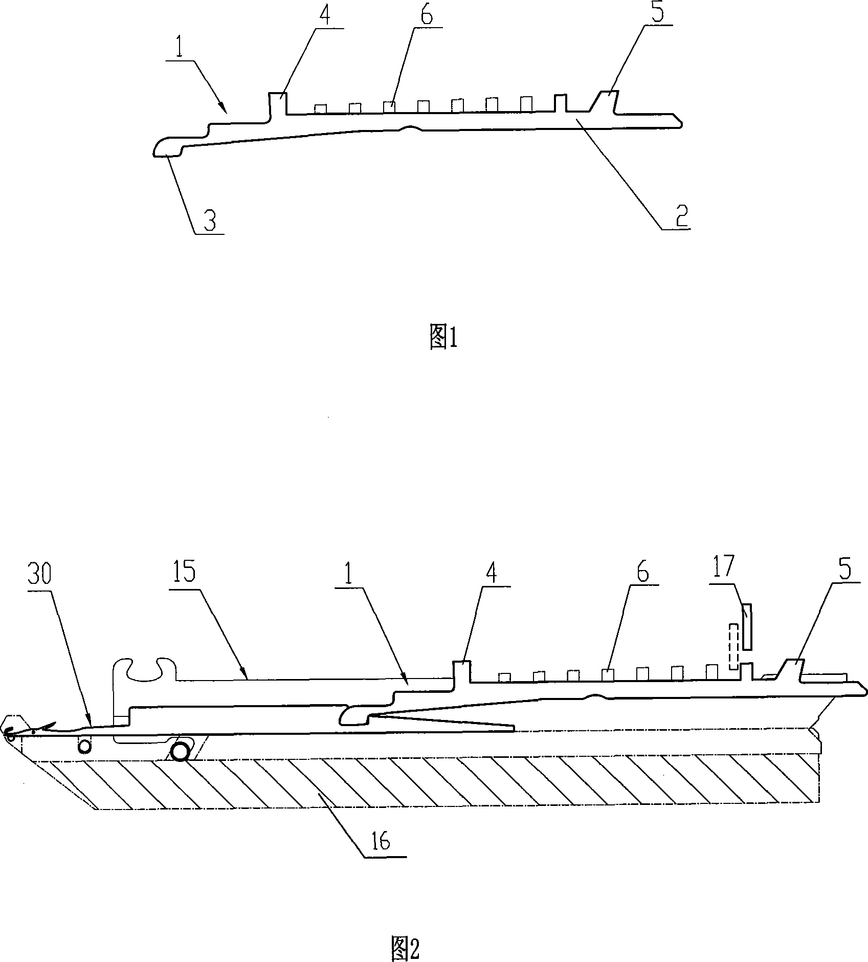
[0016] Referring to Fig. 1, the needle jack with needle selection function of the present invention is a planar sheet structure like the existing needle jack. It has a planar sheet-like base 2 , and an embedding portion 3 extends forward from the front end of the base 1 for connecting with knitting needles 30 . On the upper side of the base 2 , selector teeth 6 , front butts 4 and rear butts 5 extend upward.

[0017] Referring to Fig. 2, the needle jack 1 with the structure of the present invention is placed in a needle groove 15 on the needle plate, and the embedding part 3 at its front end is inlaid with the knitting needle 30, and only the knitting needle 30 and the needle jack are in the needle groove 15. 1. The length of the needle groove 15 is greatly shortened, so that the corresponding size of the needle plate and the needle bed can be greatly reduced...


PUM


Abstract

The invention relates to a jack with the function of selecting needle, comprising a planar laminar basal; wherein, a scarf joint for connecting with knitting needle is arranged at the front of the basal; a front needle butt and a back needle butt for triangle pushing are arranged on the top of the basal. The needle selecting tooth for selecting needle is arranged between the front needle butt and the back needle butt. The jack with the function of selecting needle has the advantages of reducing the number of the assistant stitch that just one assistant stitch is needed, reducing the length of the needle slot, which reduces the size of the whole machine and consumables greatly, and simplify the head controlling the assistant stitch, such as no pressing device is needed which not only reduces the manufacturing cost, but also makes the needle work more stably and reliably.

Description

technical field [0001] The invention relates to a computerized flat knitting machine, more specifically to a needle jack with a needle selection function in a computerized flat knitting machine. Background technique [0002] In the existing computerized flat knitting machine, the knitting action of its knitting needle is promoted by a group of auxiliary stitches. Figure 3 shows the combination of knitting needles and a group of auxiliary stitches in each needle groove on the needle bed of the existing computerized flat knitting machine. The knitting needle 30 is placed on the front side of the needle groove 15, and the front end of the needle jack 40 is embedded on the knitting needle 30, so that the two are connected as one. The tail of the needle jack 40 is supported on the bottom of the needle groove 15, the pattern piece 50 is placed on the upper side of the needle jack 40, the needle selector 20 is placed on the upper side of the pattern piece 50, and the lower butt 24...

Claims


Application Information

Patent Timeline
IPC IPC(8): D04B15/00
Inventor 冯加林巫友群
Owner 冯加林
Why Eureka
Try Eureka