
Electromagnetic displacement control valve in clutchless type variable displacement compressor

A technology with no clutch and electromagnetic capacity, which is applied in liquid displacement machinery, pump control, machine/engine, etc. It can solve the problems of reducing refrigerant and increasing the inclination angle of the swash plate

Inactive Publication Date: 2008-07-23
TOYOTA IND CORP
View PDF2 Cites 2 Cited by
  • Summary
  • Abstract
  • Description
  • Claims
  • Application Information

AI Technical Summary

Problems solved by technology

However, in the conventional electromagnetic capacity control valve, if the valve body vibrates at the maximum opening degree, the refrigerant flow rate delivered to the control pressure chamber will decrease, which may increase the inclination angle of the swash plate

Method used


Image

  • Electromagnetic displacement control valve in clutchless type variable displacement compressor
  • Electromagnetic displacement control valve in clutchless type variable displacement compressor
  • Electromagnetic displacement control valve in clutchless type variable displacement compressor

Examples


Embodiment Construction

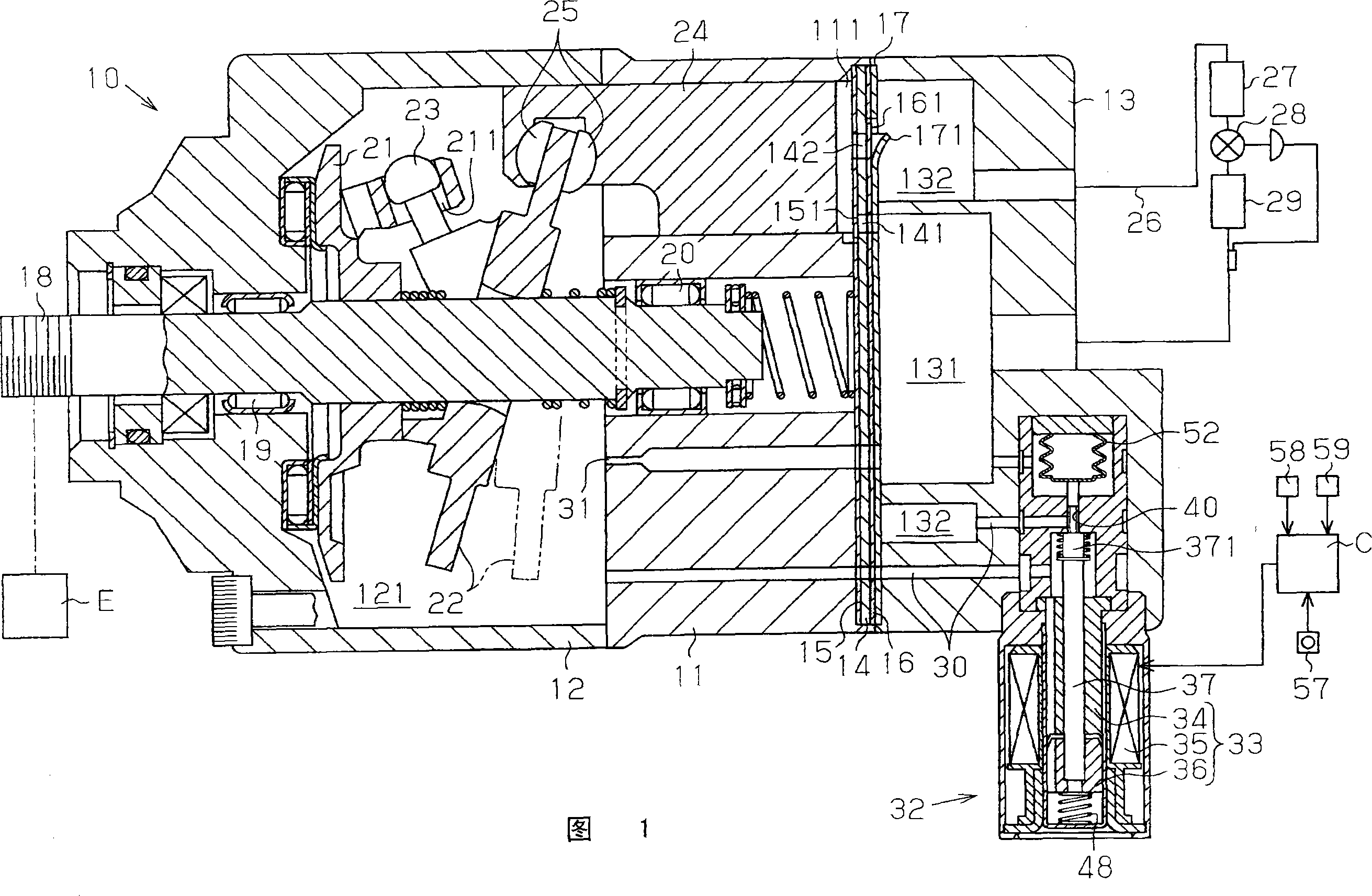
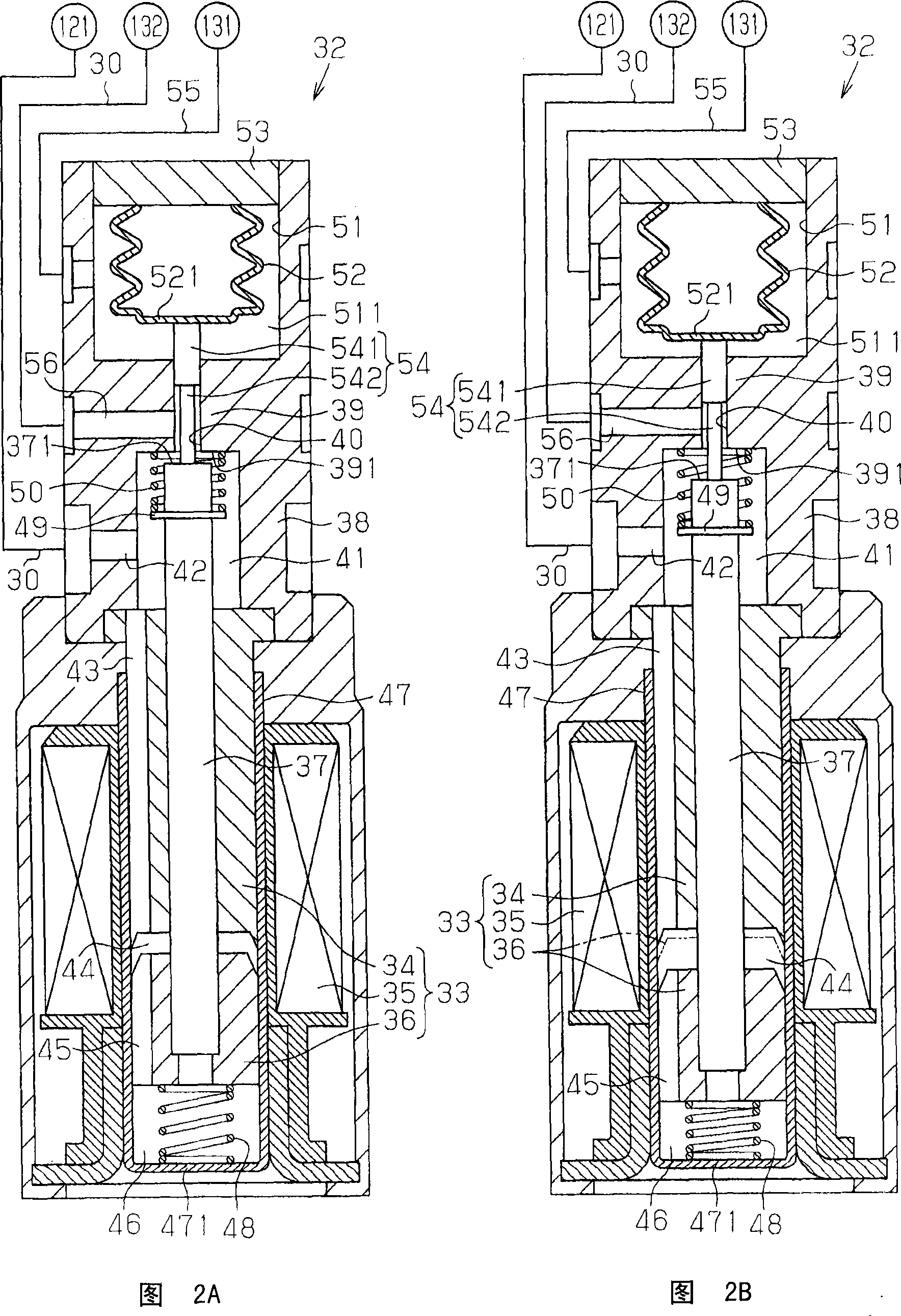
[0013] A first embodiment of the present invention will be described with reference to FIGS. 1 to 2B.

[0014] As shown in FIG. 1 , the casing of the variable capacity compressor 10 includes a cylinder block 11 , a front casing member 12 , and a rear casing member 13 . The front housing member 12 is mounted to the front end of the cylinder body 11, the rear housing member 13 is mounted to the rear end of the cylinder body 11, and the valve plate 14, valve disc plates 15, 16, and retaining plate 17 are installed therebetween. The cylinder block 11 , the front casing member 12 and the rear casing member 13 are constituted in the casing of the compressor 10 . The compressor 10 constitutes a part of an air conditioner fitted to, for example, a vehicle.

[0015] The front housing member 12 and the cylinder block 11 define a control pressure chamber 121 . The front housing member 12 and cylinder block 11 rotatably support a rotary shaft 18 via radial bearings 19 , 20 . The rotary...


PUM


Abstract

Disclosed is an electromagnetic capacity control valve in a clutchless variable capacity compressor. The control valve includes a valve body, an electromagnetic drive device, a buffer spring and a push spring. The electromagnetic driving device drives the valve body toward the position of closing the valve hole. The buffer spring pushes the valve body toward the position to close the valve hole. The pushing spring pushes the valve body away from the position of closing the valve hole by overcoming the elastic pushing force of the buffer spring. In the state where no current is supplied to the electromagnetic drive device, the valve body can overcome the elastic driving force of the buffer spring and move away from the position where the valve hole is closed.

Description

technical field [0001] The invention relates to an electromagnetic capacity control valve in a clutchless variable capacity compressor. Background technique [0002] Japanese Patent Application Laid-Open Nos. 10-205444 and 2001-173556 respectively disclose a variable capacity compressor in which refrigerant in a discharge chamber (discharge pressure area) is sent into a control pressure chamber through a supply passage, and the control pressure The refrigerant in the chamber is released to the suction pressure area through the release channel, thereby adjusting the pressure in the control pressure chamber. The pressure in the control pressure chamber is adjusted by changing the opening degree of the electromagnetic capacity control valve located in the supply channel. When the opening degree of the capacity control valve increases, the flow rate of refrigerant supplied from the discharge chamber to the control pressure chamber increases, and thus the pressure of the control...

Claims


Application Information

Patent Timeline
IPC IPC(8): F04B27/14F04B27/12F04B39/10F04B49/22F16K31/06
CPCF04B27/1804F04B2027/1827F04B2027/1854F04B2027/1859F04B27/08F04B27/14
Inventor 梅村聪广濑达也桥本友次小田和孝
Owner TOYOTA IND CORP
Learn More