
Cooling device for unit oscillating internal combustion engines

A cooling device and swing type technology, which is applied to the cooling of the engine, the arrangement of the internal combustion propulsion device, the cooling combination of the power plant, etc., can solve the problems of difficulty in ensuring the inclination angle, poor ground contact of the occupant's feet, and increased protruding amount. , to achieve the effect of ensuring the inclination angle

Active Publication Date: 2018-06-05
HONDA MOTOR CO LTD
View PDF8 Cites 0 Cited by
  • Summary
  • Abstract
  • Description
  • Claims
  • Application Information

AI Technical Summary

Problems solved by technology

[0005] In the recent unit swing type internal combustion engine, generally, in the side view of the vehicle, the axis of the rear wheel axle is at a lower position than the crankshaft, and the internal combustion engine is positioned forward and upward. In the above-mentioned Patent Document 1, a movable louver is adopted The rear of the frame, that is, the rear of the fan cover is provided with a link mechanism. Therefore, in a unit swing type internal combustion engine in which the internal combustion engine is arranged at the lower part of the vehicle, the amount of protrusion of the cooling device toward the bottom of the internal combustion engine becomes large, and it is difficult to secure an inclination angle.
Therefore, countermeasures such as raising the height of the vehicle are necessary, and there is a possibility that the problem of poor contact of the occupant's feet with the ground may arise.

Method used


Image

  • Cooling device for unit oscillating internal combustion engines
  • Cooling device for unit oscillating internal combustion engines
  • Cooling device for unit oscillating internal combustion engines

Examples


Embodiment Construction

[0093] Next, an embodiment of the present invention will be described with reference to the drawings. Note that, in the description, descriptions of directions such as front, rear, left, right, and up and down are assumed to be the same as directions relative to the vehicle body unless otherwise specified. In addition, the symbol FR shown in each figure represents the front of the vehicle body, the symbol UP represents the upper side of the vehicle body, and the symbol LH represents the left side of the vehicle body.

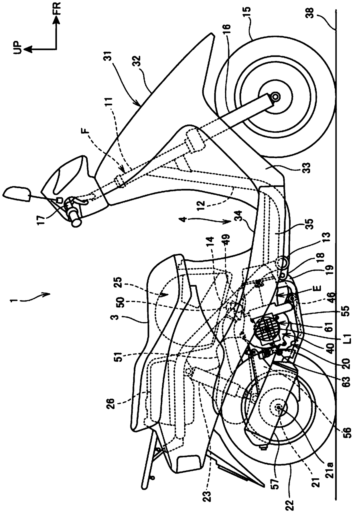
[0094] figure 1 It is a right side view of a motorcycle 1 equipped with a unit swing type internal combustion engine E of the present invention.

[0095] The motorcycle 1 is equipped with a power unit 20 including a unit swing type internal combustion engine E, and is a saddle-riding type pedal-type small vehicle in which a rider sits astride a seat 3 .

[0096] The body frame F of the motorcycle 1 includes a front pipe 11 constituting a front end, a downpipe ...


PUM


Abstract

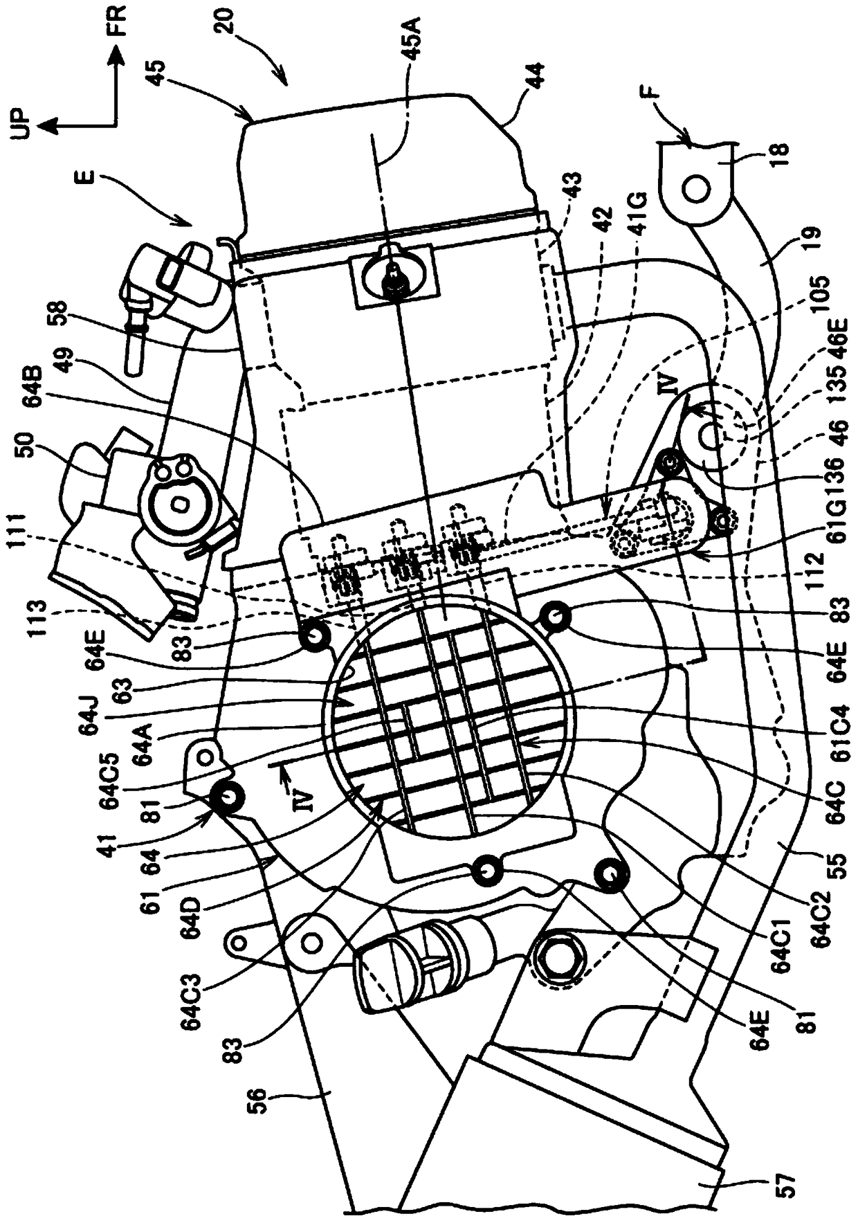
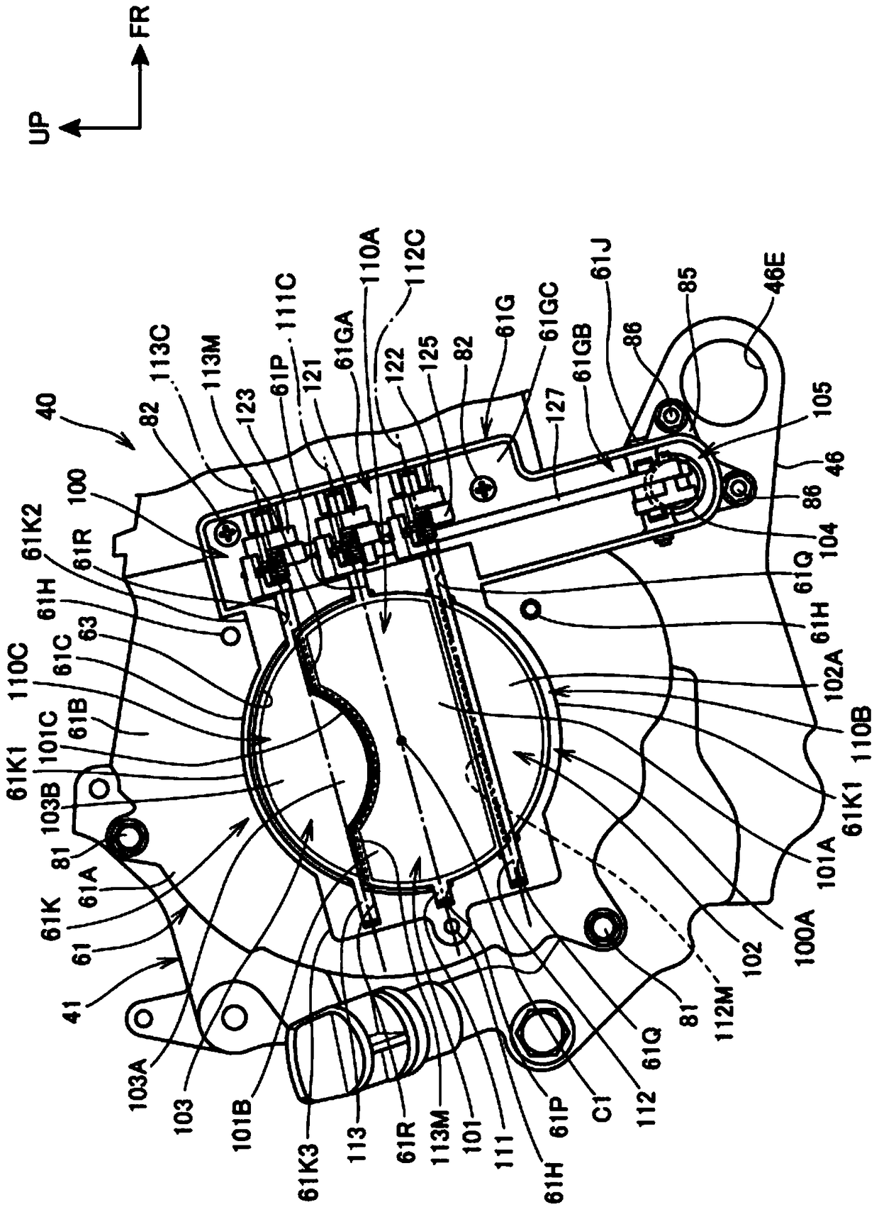
A cooling device for a unit swing type internal combustion engine capable of easily securing a bank angle of a vehicle is provided. The cooling device comprises a fan cover (61) provided with a cooling air suction inlet (63) for taking in outside air; a movable louver (100A), first-third heat dissipation plates (101-103) rotating with first-third rotating shafts (111-113) arranged at the cooling air suction inlet (63) as the centers to close and open the cooling air suction inlet (63); a power transmission mechanism (105) transmitting power of a transmitter (104) to the movable louver (100A). In a lateral view of a vehicle, the axis of a rear wheel axle is lower than the axis of a bent axle; the axes (111C-113C) of the first-third rotating shafts (111-113) point to the front-rear direction of the vehicle; supported on the fan cover (61), the power transmission mechanism (105) is connected with the front portions of the first-third rotating shafts (111-113) and is arranged in front of the cooling air suction inlet (63).

Description

technical field [0001] The present invention relates to a cooling device for a unit swing type internal combustion engine provided with a cooling fan that sucks in external air by rotating in conjunction with a crankshaft. Background technique [0002] As a cooling device for a conventional unit swing type internal combustion engine, it includes a cooling fan, a fan cover, and a movable louver. The cooling fan rotates in conjunction with the crankshaft to suck in external air. The above-mentioned movable ventilation window is arranged on the cooling air inlet of the fan cover, and its heat dissipation plate rotates around the fulcrum parallel to the opening surface of the cooling air inlet to open and close the cooling air inlet. A cooling device for a unit swing type internal combustion engine is known (for example, refer to Patent Document 1). [0003] In the fan cover in this technology, a movable ventilation window frame is formed to support the shaft so that it points ...

Claims


Application Information

Patent Timeline
Patent Type & Authority Patents(China)
IPC IPC(8): B60K11/06B60K5/12B60K13/04F01P7/02B62J99/00
CPCB60K5/12B60K11/06B60K13/04B62J45/40B62J99/00F01P7/026F01P2025/08F01P2050/16
Inventor 小林友和高姓一行伊藤祯昭
Owner HONDA MOTOR CO LTD
Learn More