Apparatus and method for detecting filters lustration degree

A detection equipment and detection method technology, applied in the directions of cleaning methods and utensils, chemical instruments and methods, measuring devices, etc., can solve the problems of decreased product yield, unavailability of products, waste of time, etc., to avoid wasting time and convenient. and accurate detection

Inactive Publication Date: 2008-07-23
HONG FU JIN PRECISION IND (SHENZHEN) CO LTD +1
View PDF0 Cites 20 Cited by
  • Summary
  • Abstract
  • Description
  • Claims
  • Application Information

AI Technical Summary

Problems solved by technology

During the coating process, the cleanliness of the filter will be affected by many factors, such as electron gun, vacuum chamber, coating substrate, etc. All aspects will cause white spots in the film layer of the finished product after coating. Too much, it will not be used on the product because the cleanliness is too low
Therefore, the coated filter needs to be tested for cleanliness, o

Method used


Image

  • Apparatus and method for detecting filters lustration degree
  • Apparatus and method for detecting filters lustration degree

Examples


Embodiment Construction

[0011] The embodiments of the present invention will be further described in detail below in conjunction with the accompanying drawings.

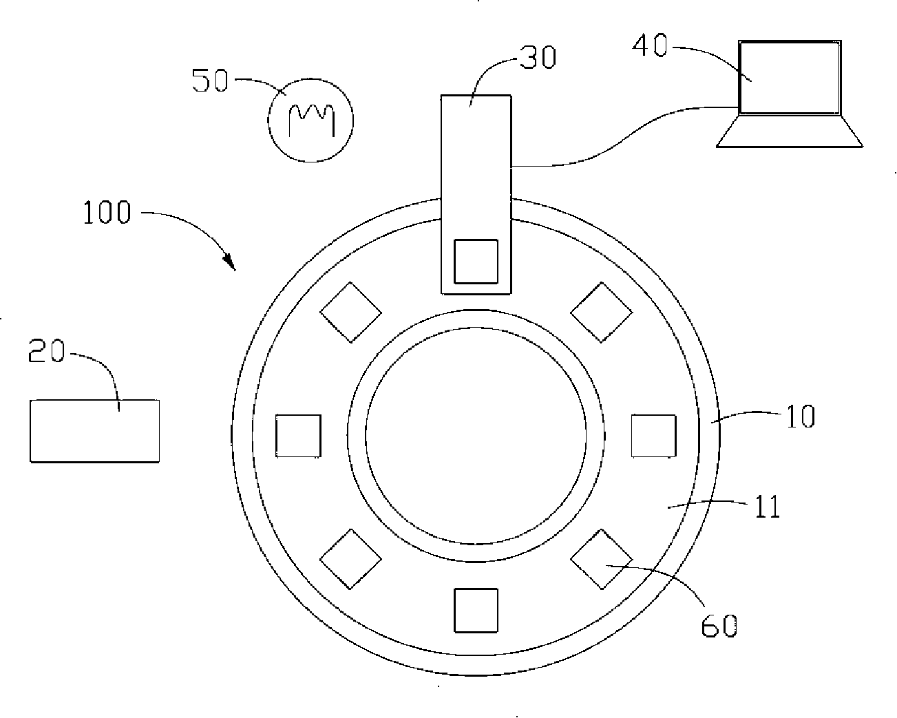
[0012] see figure 1 , the embodiment of the present invention provides a detection device 100 for the cleanliness of an optical filter. The detection equipment includes a base 10 , a dust removal device 20 , an image acquisition device 30 , and an image processing and analysis system 40 .

[0013] The base 10 further includes a conveyor belt 11 . The conveyor belt 11 moves in one direction at a certain speed. In this embodiment, the conveyor belt 11 moves clockwise. The optical filter 60 to be tested is put in from the right side of the base 10 , conveyed by the conveyor belt 11 , and passes through the corresponding positions of the dust removal device 20 and the image acquisition device 30 in turn, so that the entire detection process can be realized.

[0014] The dust removal device 20 is an ion air gun, and the air outlet of the ion...


PUM


Abstract

The invention relates to a check device of color filter cleanness, which comprises a base table (10), a dust cleaner (20), an image acquisition device (30) and an image processing and analyzing system (40), wherein the base table carries an object color filter (60), the dust cleaner removes the dust on the surface on the color filter, the image acquisition device obtains and outputs the image information of the color filter, the image processing and analyzing system receives and processes the image information of the color filter output from the image acquisition device to judge if the color filter cleanness meets a preset standard value. The inventive device can realize automatic check of color filter cleanness and improve check efficiency and accuracy. The invention further provides a check method of color filter cleanness.

Description

technical field [0001] The invention relates to a manufacturing process of an optical filter, in particular to a detection device and method for the cleanliness of an optical filter. Background technique [0002] Generally, various optical lenses (Lens), optical filters and other optical components of optical products such as cameras, digital cameras, camera phone lens modules, etc., because it is necessary to avoid the incident light caused by the reflection of part of the incident light when it passes through each component. Light energy loss needs to be coated with anti-reflective coating on both sides of each optical lens, or coated with a film that can filter out a certain section of light (such as infrared filter, ultraviolet filter) on one side of the filter, and The other side is coated with an anti-reflection film, and these optical films are used to increase the anti-reflection performance of the optical element and prevent light energy loss. [0003] The coating ...

Claims


Application Information

Patent Timeline
IPC IPC(8): G01N21/958B08B6/00
Inventor 凌维成
Owner HONG FU JIN PRECISION IND (SHENZHEN) CO LTD
Why Eureka
Try Eureka