
Transient flame detection method based on image processing

A flame detection and image processing technology, applied in the field of flame detection, can solve the problems of poor measurement accuracy, poor measurement repeatability, joint analysis of the overall distribution law of no flame, etc., and achieve the effect of improving measurement accuracy

Active Publication Date: 2014-03-05
NANJING UNIV OF SCI & TECH
View PDF4 Cites 20 Cited by
  • Summary
  • Abstract
  • Description
  • Claims
  • Application Information

AI Technical Summary

Problems solved by technology

At present, the flame test methods at home and abroad mainly include the camera door B waiting method and the rotary drum photography method. The camera B door waiting method takes the cumulative photos of the flame in the transient flame within its duration, and can analyze the flame as a whole. The drum photography method uses a drum camera to shoot transient flames. The two methods can only qualitatively analyze the overall spatial distribution and strength of the flame in the whole time. Quantitative measurement requires manual testing with measuring tools, and the testing process is complicated. It is cumbersome, and the measurement repeatability is not good, and the measurement accuracy is poor
[0003] More Chinese invention patents disclose the application of image processing methods to detect flames, such as Chinese invention patents (publication numbers CN1308224A, CN102034110A, CN101441712A, CN101840571A, etc.), the purpose of flame detection in the above patents is to detect whether there is flame in the video shooting area As a result, the specific image processing method does not aim at detecting the relevant parameters of the transient flame area, and does not jointly analyze the overall distribution of the flame over the entire time period, and the flame detection in the above patents is completed by ordinary cameras, while The duration of the transient flame is extremely short (the occurrence time is at the millisecond level), and the frame rate of ordinary cameras cannot meet the requirements of on-site recording and scene playback

Method used


Image

  • Transient flame detection method based on image processing
  • Transient flame detection method based on image processing
  • Transient flame detection method based on image processing

Examples


Embodiment Construction

[0033] The following takes a certain transient flame video shooting and analysis process as an example to illustrate the specific implementation method, wherein the transient flame generating device is a cannon.

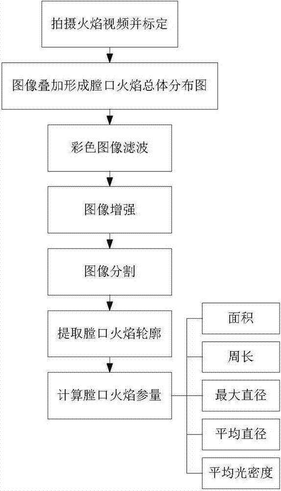
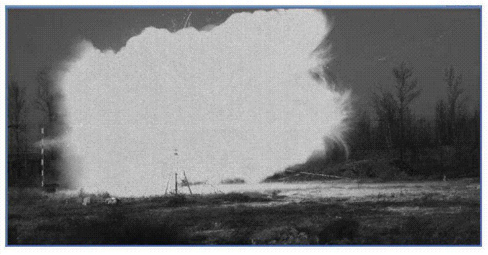
[0034] Step 1: Take a video of the transient flame. The high-speed camera is placed at an appropriate distance from the muzzle, and the entire transient flame area is required to cover 2 / 3 or more of the field of view of the high-speed camera. The camera is perpendicular to the firing direction of the muzzle, and a calibration rod is set up in the opposite direction of the muzzle firing direction. It is used to calibrate the image pixel and the actual size. The high-speed camera is used to shoot the transient flame video. When the shell is fired, the high-speed camera is triggered to shoot. Because the high-speed camera has a high frame rate, the first frame or even several frames in the video are not included. Background image of transient flame I B , the video con...


PUM


Abstract

The invention discloses a transient flame detection method based on image processing. A high-speed camera is adopted to shoot a transient flame video and completely records the dynamic development process of transient flame; an overall distribution image of the transient flame is obtained in an image superposition method; an image enhancement method according with a transient flame color space distribution rule is put forward, a transient flame area is brightened, and a background area is darkened; image processing methods such as image filtering, image enhancement, image segmentation and image contour extraction are used comprehensively to extract the transient flame area, and the area, the perimeter, the largest diameter, the average diameter, average optical density and other parameters of the transient flame area are calculated to provide effective data and technical support for development and performance testing of artillery, combustion explosives, gun propellants and the like.

Description

technical field [0001] The invention belongs to the field of flame detection, and in particular relates to a method for extracting a transient flame area and measuring flame parameters by using a digital image processing method. Background technique [0002] After detonating or firing ammunition for airtight explosives, artillery and other equipment, transient flames will inevitably be formed in the explosives and muzzle, reflecting incomplete combustion of the gunpowder and a decrease in energy utilization, thus affecting the actual application performance of such equipment , in order to improve these influences of transient flames, it is necessary to conduct in-depth research on transient flames, so how to detect transient flames and judge the size and strength of flames are very important. At present, the flame test methods at home and abroad mainly include the camera door B waiting method and the rotary drum photography method. The camera B door waiting method takes the ...

Claims


Application Information

Patent Timeline
Patent Type & Authority Applications(China)
IPC IPC(8): G06T7/20
Inventor 商飞孔德仁王芳狄长安贾云飞
Owner NANJING UNIV OF SCI & TECH
Learn More